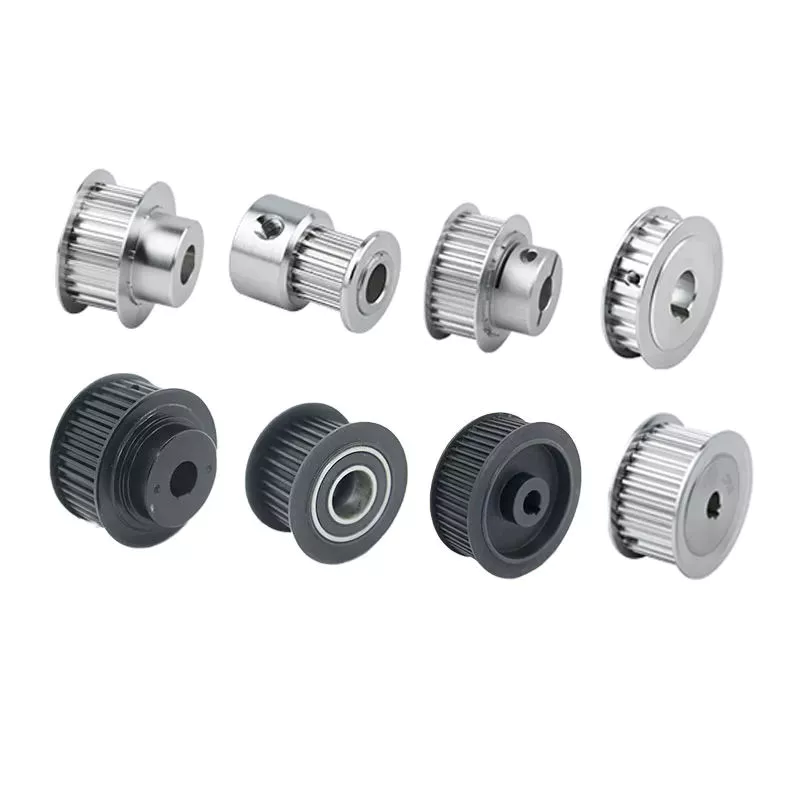
Product Description
Product Description
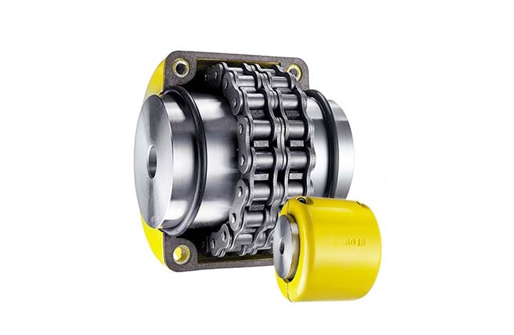
Hot Selling GL Type Spline Rigid Shaft Couplings Roller Chain Coupling For Industry Machine
FEATURES
Manufactured according to relevant industrial standards
Available in many sizes, ratings, and product types, including flexible shaft couplings and OK couplings
Fabricated from a variety of high-grade steel
BENEFITS
Several surface treatment processes protect against corrosion
Customized products are available
Large couplings withstand very high torque
Flexible shaft couplings compensate for shaft misalignment
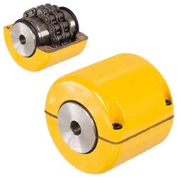
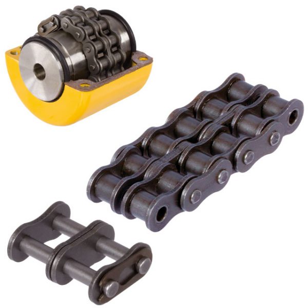
The chain coupling consists of two-strand roller chains, 2 sprockets and AL-Alloy cover, features simple and compact structure, and high flexibility, power transmission capability and durability.
What’s more ,the chain coupling allows simple connection/disconnection, and the use of the housing enhances safety and durability.
Advantages:
1. Material: C45 steel, Aluminum, Rubber and plastic etc.
2. High efficiency in transmission
3. Finishing: blacken, phosphate-coat, and oxidation.
4. Different models suitable for your different demands
5. Application in wide range of environment.
6. Quick and easy mounting and disassembly.
7. Resistant to oil and electrical insulation.
8. Identical clockwise and anticlockwise rotational characteristics.
9. Small dimension, low weight, high transmitted torque.
10. It has good performance.
| Partnerships Reliable Supply-Chain: |
Based on our experienced team and strict, effective supply chain management, Granville products deliver premium quality, and performance our customers have relied on for years. From a full range of bearings, mounted bearing units, power transmission products, and related markets around the world, we provide the industry’s most comprehensive range of qualified products available today.
Advantage Manufacturing Processesand Quality Control:
01 Heat Treatment
02 Centerless Grinding Machine 11200 (most advanced)
03 Automatic Production Lines for Raceway
04 Automatic Production Lines for Raceway
05 Ultrasonic Cleaning of Rings
06 Automatic Assembly
07 Ultrasonic Cleaning of Bearings
08 Automatic Greasing, Seals Pressing
09 Measurement of Bearing Vibration (Acceleration)
10 Measurement of Bearing Vibration (Speed)
11 Laser Marking
12 Automatic Packing
1 Prevent from damage.
2. As customers’ requirements, in perfect condition.
3. Delivery : As per contract delivery on time
4. Shipping : As per client request. We can accept CIF, Door to Door etc. or client authorized agent we supply all the necessary assistant.
FAQ
Q 1: Are you a trading company or a manufacturer?
A: We are a professional manufacturer specializing in manufacturing various series of couplings.
Q 2:Can you do OEM?
Yes, we can. We can do OEM & ODM for all the customers with customized artworks in PDF or AI format.
Q 3:How long is your delivery time?
Generally, it is 20-30 days if the goods are not in stock. It is according to quantity.
Q 4: How long is your warranty?
A: Our Warranty is 12 months under normal circumstances.
Q 5: Do you have inspection procedures for coupling?
A:100% self-inspection before packing.
Q 6: Can I have a visit to your factory before the order?
A: Sure, welcome to visit our factory.
/* January 22, 2571 19:08:37 */!function(){function s(e,r){var a,o={};try{e&&e.split(“,”).forEach(function(e,t){e&&(a=e.match(/(.*?):(.*)$/))&&1
What are the common materials used in chain couplings?
Chain couplings are commonly made from various materials that offer the necessary strength, durability, and wear resistance required for transmitting torque between shafts. The choice of materials depends on factors such as the application requirements, operating conditions, and the specific design of the coupling. Here are some common materials used in chain couplings:
- Steel: Steel is one of the most widely used materials for chain couplings. It offers excellent strength, toughness, and resistance to wear and fatigue. Carbon steel and alloy steel are commonly used, with alloy steel providing enhanced properties such as higher tensile strength and improved corrosion resistance.
- Stainless Steel: Stainless steel is chosen for chain couplings when corrosion resistance is a critical requirement. It offers good mechanical properties along with resistance to rust and corrosion, making it suitable for applications in harsh environments or where exposure to moisture or chemicals is present.
- Cast Iron: Cast iron is occasionally used for chain couplings, particularly in applications where cost-effectiveness and moderate strength are important factors. Cast iron provides good wear resistance and can withstand moderate loads and operating conditions.
- Bronze: Bronze is utilized in certain specialized chain couplings, especially in applications where self-lubrication and high resistance to corrosion are required. Bronze has good friction properties and can operate in conditions where lubrication may be limited or unavailable.
- Plastics: In some cases, certain plastics, such as nylon or polyurethane, are used for chain coupling components like chain guides or protective covers. Plastics offer low friction, noise reduction, and resistance to chemicals, making them suitable for specific applications.
It’s important to note that the materials used in chain couplings may vary depending on the specific manufacturer, coupling design, and application requirements. It is recommended to consult the manufacturer’s specifications and guidelines to determine the appropriate materials for a particular chain coupling.
Additionally, in some cases, chain couplings may incorporate a combination of different materials, such as steel for the sprockets and roller chain, and elastomers for the flexible elements. This hybrid construction allows for optimized performance, balancing strength, flexibility, and damping characteristics.
Overall, the selection of materials for chain couplings is crucial to ensure reliable and efficient power transmission while considering factors such as load capacity, operating conditions, and the desired service life of the coupling.
Can chain couplings accommodate angular misalignment?
Yes, chain couplings are designed to accommodate a certain degree of angular misalignment between the connected shafts. Angular misalignment refers to the situation where the axes of the two shafts are not perfectly aligned and form an angle with each other.
Chain couplings are flexible in nature, and their design allows for some degree of angular displacement. The flexibility is primarily provided by the roller chain, which can bend and adjust to a certain extent to accommodate the misalignment. This flexibility helps to reduce the stress on the coupling components and allows for smoother operation even in the presence of angular misalignment.
However, it is important to note that chain couplings have limitations in terms of angular misalignment. Excessive angular misalignment beyond the specified limits can lead to increased stress, accelerated wear, and potential coupling failure. The manufacturer’s specifications and guidelines should be followed to ensure that the angular misalignment remains within the acceptable range for the specific chain coupling being used.
Regular inspection and maintenance of the chain coupling are also essential to identify and address any misalignment issues. If significant angular misalignment is detected, corrective measures should be taken, such as realigning the shafts or considering alternative coupling options that are better suited for the specific misalignment requirements.
It is worth mentioning that chain couplings are more tolerant of angular misalignment compared to some other types of couplings, such as rigid or gear couplings. However, it is still important to strive for proper alignment during installation and minimize any excessive misalignment to ensure optimal performance, reliability, and longevity of the chain coupling and the connected machinery or equipment.
How to select the right chain coupling for a specific application?
Choosing the appropriate chain coupling for a specific application involves considering various factors to ensure optimal performance and reliable power transmission. Here are some key steps to guide you in the selection process:
-
Identify Application Requirements: Begin by understanding the specific requirements of the application. Consider factors such as the torque load, speed, misalignment conditions (angular, parallel, axial), and environmental conditions (temperature, moisture, presence of corrosive substances).
-
Determine Torque and Speed Requirements: Calculate or estimate the torque and speed requirements of the application. This information is crucial in selecting a chain coupling that can handle the transmitted torque and operate effectively at the required speed range.
-
Evaluate Misalignment Compensation: Assess the expected misalignment conditions in the application. Determine the magnitude of angular, parallel, and axial misalignments that the chain coupling needs to tolerate. This will help in selecting a coupling design that can accommodate the anticipated misalignment without compromising performance or causing excessive stress on the machinery.
-
Consider Space Limitations: Evaluate the available space for the chain coupling. Measure the shaft-to-shaft distance and ensure that the selected coupling can fit within the available space without interference with other components or structures.
-
Assess Environmental Factors: Take into account the environmental conditions in which the chain coupling will operate. Consider factors such as temperature extremes, humidity, presence of dust or debris, and exposure to corrosive substances. Choose a chain coupling that is designed to withstand these conditions and is made from materials that offer adequate corrosion resistance.
-
Consult Manufacturer Specifications: Review the specifications and technical information provided by reputable chain coupling manufacturers. Pay attention to factors such as torque ratings, speed limits, misalignment capabilities, material compatibility, and recommended maintenance practices.
-
Consider Maintenance Requirements: Evaluate the maintenance requirements of the chain coupling. Assess factors such as lubrication needs, ease of inspection, and adjustment procedures. Choose a coupling that aligns with the maintenance capabilities and resources available in your application.
-
Seek Expert Advice if Needed: If you are uncertain about the selection process or have specific application requirements that need expert guidance, consult with knowledgeable engineers or technical representatives from the coupling manufacturer. They can provide valuable insights and recommendations based on their expertise and experience.
By following these steps and considering the specific application requirements, you can select the right chain coupling that meets the torque, speed, misalignment, space, and environmental demands of your application. Proper selection will ensure efficient power transmission, reliable operation, and extended lifespan of the chain coupling.


editor by CX 2024-05-06
China manufacturer OEM ODM Customized Aluminum Die Casting Housing of Belt Tension Pulley pulley and belt
Product Description
Company Profile
Hongxin is IATF16949 ceritficated and professional in designing and manufacturing molds,producing prototype, precision high-pressure aluminum alloy die casting parts,zinc alloy high-pressure die casting parts, precision CNC parts and precision plastic injection parts.
Product Description
| Technical parameters | Aluminum alloy die casting: ADC12/A360/A380/Alsi9cu3/Alsi12Cu1Fe/Alsi12Fe |
| Zinc alloy die casting:ZA3#,ZA5#,ZA8# | |
| Plastic injection: PA6/PA66/ABS/PC/POM/PE | |
| Aluminum alloy profile extrusion: 6061/6063/6082/7075 | |
| CNC machining and Turnning: 6061/6063/5052 | |
| Part Weight: From 10g to 50000g | |
| Manufacture Process | Drawing/Sample→Mold→Die casting→Deburring → Polishing→CNC Machining→Surface Finishing→ Assembly →Quality Inspection→Packaging→Delivery |
| Equipment | Cold chamber die casting machine:180T/280T/350T/500T/800T/1250T |
| Injection machines: 88T/128T/160T/250T/380T/500T | |
| CNC centers, CNC turning, CNC lathes, electrical pulse, line cutting, milling, drilling, grinding | |
| Surface Treatment | Trimming, Deburring,Polishing, Shot blasting, Sandblasting,Tumbling, Powder coating, Anodizing, Chrome, Electrophoresis, Passivation, Chemical coating |
| Software | Pro-e/Solid work/UG/Auto CAD/CATIA |
| Products Application | Automotive, Electric Motor, Light, Motorcycle,Bicycle, Power tool, Telecommunication, Gas Meter, Home Appliance Equipment, Compressors, Flow Meters, Pumps, Valves, Traffic Equipment, etc. |
Our Advantages
- Direct manufacturer, lower cost and quicker feedback
- Specialist in prototyping, help you fast verify your design
- Specialist in low quantity orders (no MOQ requirement for aluminum CNC parts)
- Specialist in one-step production services from designing to assembly
Facility capability
Samples
FAQ
| Q1. Where is your company? |
| A:Our company is located in HangZhou City, ZHangZhoug province, which is known as the hometown of mold |
| Q2. Are you a factory or trading company? |
| A: We are a direct and professional factory and specialized in die casting industry since 2011. |
| Q3.Can your company make by sample? |
| A: Yes, we can make by both the sample and drawing. |
| Q4. What do I need to provide if I want to customize products and get a offer? |
| A: You can send 2D & 3D drawing(.step/.stp/.igs/.dwg is prefer) or samples and detailed requirement to our team. |
| Q5. What’s the process of Customizing product? |
| A: 1. Design of product drawings/samples. 2. Confirm the drawing with the customer. 3. Make the mold. 4. Send sample to customer for approval. 5. Receive confirmation from customer and series production. 6. Quality inspection 7. Packing and shipping. |
| Q6. Can your company make the mold? |
| A: Yes, design mold and make mold and fixture by ourselves. |
| Q7. Your company’s yearly production capacity? |
| A: 200 set of molds, 5 Million die casting parts and aluminum extrusion parts, 1 Million plastic injection parts |
| Q8. What is the minimum order quantity? |
| A:No MOQ for aluminum CNC parts. Low MOQ can be provided to help you test market. |
| Q9. How long is the lead time? |
| A: Depends on the order quantity. 1 week for prototypes,Normally 3-7 weeks for mold, 2-4 weeks for series production parts. |
| Q10. How do you package the products? |
| A: Bubble bag – Carton Box – Wooden pallet. Special packaging method can be accepted. |
| Q11. What is the payment method? |
| A: T/T, WEST UNION, PAYPAL. |
| Q12.How is the quality? |
| A: Strict control before shipment. |
| Q13: What if I got some defective products? |
| A:If you find any defective products, we will exchange good products or refund you immediately. If you have any questions, please feel free to contact us. |
/* January 22, 2571 19:08:37 */!function(){function s(e,r){var a,o={};try{e&&e.split(“,”).forEach(function(e,t){e&&(a=e.match(/(.*?):(.*)$/))&&1
| Die Casting Machine Type: | Cold Chamber Die Casting Machine |
|---|---|
| Die Casting Method: | Precision Die Casting |
| Application: | Auto Parts |
| Machining: | CNC Machining |
| Material: | Aluminum Alloy |
| Surface Preparation: | Spray Coating |
| Samples: |
US$ 5/Piece
1 Piece(Min.Order) | |
|---|
| Customization: |
Available
| Customized Request |
|---|
How do pulleys contribute to the operation of conveyor systems?
Pulleys play a critical role in the operation of conveyor systems by facilitating the movement of materials or products along the conveyor belt. Here’s how pulleys contribute to the functioning of conveyor systems:
1. Power Transmission: Conveyor systems typically utilize a motorized pulley, also known as a drive pulley or head pulley, which is connected to an electric motor. The motor rotates the drive pulley, which in turn moves the conveyor belt. The rotational power from the motor is transmitted to the belt through the drive pulley, enabling the continuous movement of the belt and the materials being conveyed.
2. Belt Tension and Tracking: Pulleys are used to maintain proper tension in the conveyor belt. Tension pulleys, also called idler pulleys, are strategically placed along the conveyor system to apply tension to the belt. These pulleys help to keep the belt taut and prevent slippage or sagging. Additionally, tracking pulleys are used to align the conveyor belt, ensuring it stays centered and runs smoothly along the intended path.
3. Load Support: Pulleys provide support for the conveyor belt and the load it carries. The belt wraps around the pulleys, and the load is distributed over the surface of the belt. Pulleys with larger diameters are often used at points where heavy loads are encountered to help distribute the load more effectively and prevent belt deformation or damage.
4. Directional Changes: Conveyor systems may require changes in direction to accommodate the layout or specific processing needs. Pulleys known as bend pulleys or snub pulleys are used to redirect the belt and change its course. These pulleys are designed to guide the belt smoothly around bends or corners without causing excessive stress or strain on the belt.
5. Speed Control: Pulleys can be utilized for speed control in conveyor systems. By using pulleys of different sizes or by employing variable speed drives, the rotational speed of the drive pulley can be adjusted, affecting the speed at which the conveyor belt moves. This allows for flexibility in the conveyance process, accommodating different material flow rates or specific operational requirements.
6. System Support and Stability: Pulleys, along with their associated support structures, provide stability to the conveyor system. They help to maintain the alignment and tension of the belt, preventing misalignment, vibrations, and excessive belt movement. Properly designed and maintained pulleys contribute to the overall reliability and smooth operation of the conveyor system.
Conveyor systems are widely used in industries such as manufacturing, mining, logistics, and warehousing. Pulleys are essential components that ensure the efficient and reliable movement of materials and products along the conveyor belt, enabling automated and continuous material handling processes.
How do pulleys contribute to the functioning of bicycles and motorcycles?
Pulleys play important roles in the functioning of both bicycles and motorcycles, aiding in power transmission, speed control, and overall mechanical efficiency. Here’s how pulleys contribute to the operation of these vehicles:
1. Bicycles:
– Derailleur System: In most modern bicycles, pulleys are used in the derailleur system. The derailleur is responsible for shifting the bicycle chain between different gears on the front and rear sprockets. Pulleys, often referred to as jockey wheels, are positioned in the derailleur to guide and tension the chain as it moves between gears. They ensure smooth and precise shifting, allowing the rider to adapt to various terrains and maintain an optimal pedaling cadence.
– Belt Drive Systems: Some bicycles use a belt drive instead of a traditional chain drive. Belt drives employ a pulley system that consists of a front pulley attached to the pedal crank and a rear pulley attached to the rear wheel hub. The belt is wrapped around these pulleys, transferring power from the rider’s pedaling motion to propel the bicycle forward. Pulleys in belt drive systems enable efficient power transfer, reduce maintenance needs, and provide a quieter and cleaner alternative to chain drives.
2. Motorcycles:
– Clutch System: Pulleys, known as clutch pulleys, are utilized in motorcycle clutch systems. The clutch connects the engine to the transmission and allows the rider to engage or disengage power transmission to the rear wheel. When the clutch lever is pulled, the clutch pulley separates the engine’s rotational motion from the transmission, disengaging power transfer. Releasing the clutch lever brings the pulley back into contact, engaging power transmission and enabling the motorcycle to move.
– Variable Transmission Systems: Some motorcycles employ pulleys in variable transmission systems, such as continuously variable transmissions (CVT). CVTs use a pair of pulleys connected by a belt or chain. By changing the diameter of the pulleys, the CVT adjusts the gear ratio continuously, providing seamless and efficient power delivery across a wide range of speeds. Pulleys in variable transmission systems contribute to smooth acceleration, improved fuel efficiency, and enhanced riding comfort.
– Drive Belt Systems: Pulleys are also utilized in motorcycles equipped with belt drive systems. Similar to bicycles, these systems consist of a front pulley connected to the engine’s crankshaft and a rear pulley connected to the rear wheel. The belt runs around these pulleys, transferring power from the engine to the rear wheel. Belt drive systems offer advantages such as reduced maintenance, quieter operation, and smoother power delivery compared to traditional chain drives.
Overall, pulleys are integral components in bicycles and motorcycles, contributing to smooth gear shifting, efficient power transmission, and improved overall performance. Whether in derailleur systems, belt drive systems, clutch systems, or variable transmission systems, pulleys play a vital role in enhancing the functionality and ride experience of these vehicles.
Can pulleys be customized for specific applications?
Yes, pulleys can be customized to meet the specific requirements of various applications. Customization allows pulleys to be tailored to specific sizes, shapes, materials, and performance characteristics. Here’s a detailed explanation of how pulleys can be customized:
1. Size and Shape: Pulleys can be customized in terms of their size and shape to fit the specific space and layout constraints of the application. This includes variations in diameter, width, groove configuration, and overall design. Custom sizes and shapes ensure optimal fit and compatibility within the system, allowing for efficient and effective load distribution and lifting.
2. Materials: Pulleys can be customized based on the materials used for their construction. Different materials offer varying properties such as strength, durability, weight, and resistance to corrosion or wear. By selecting the appropriate materials, pulleys can be customized to withstand the specific operating conditions of the application, including temperature, humidity, and exposure to chemicals or harsh environments.
3. Bearing Systems: The bearing system of a pulley can be customized to suit the requirements of the application. Different bearing types, such as ball bearings or roller bearings, can be selected based on factors like load capacity, rotational speed, and desired friction characteristics. Customizing the bearing system ensures smooth rotation, reduced friction, and improved overall performance of the pulley.
4. Coatings and Surface Treatments: Pulleys can be customized with various coatings and surface treatments for enhanced performance. For example, pulleys used in applications that involve high temperatures may benefit from heat-resistant coatings. Pulleys used in environments with corrosive substances can be coated with protective materials to prevent corrosion. Surface treatments such as polishing or plating can also be applied to reduce friction, improve wear resistance, or provide specific surface properties.
5. Load Capacity and Performance: Pulleys can be customized to accommodate specific load capacities and performance requirements. This includes determining the number of pulleys in a system, selecting the appropriate pulley ratios, and configuring the pulley arrangement to achieve the desired mechanical advantage. Customization allows pulleys to be optimized for the specific load requirements, ensuring efficient load distribution and lifting.
6. Integration with Systems: Pulleys can be customized to seamlessly integrate with existing systems or equipment. This involves designing pulleys with compatible interfaces, mounting options, and connection methods. Customization ensures proper alignment, easy installation, and smooth operation when incorporating pulleys into the overall system.
7. Specialty Applications: In certain specialized applications, pulleys can be customized to meet unique requirements. This may include designing pulleys for extreme operating conditions, such as high speeds or heavy loads, or developing pulleys with specific features like built-in sensors or locking mechanisms. Customization allows pulleys to be tailored to the specific needs of niche applications.
Customization of pulleys is typically carried out by manufacturers or suppliers who have the expertise and capabilities to design and produce pulleys according to specific customer requirements. This allows for the optimization of pulley performance, compatibility, and efficiency in a wide range of applications.


editor by CX
2024-05-06
China best High Quality Declutchable Accessories Manual Override Gearboxes with Great quality
Product Description
High Quality Declutchable Accessories Manual Override Gearboxes
Features
- Compact and light weight
- ISO 5211 mounting pattern
- Machined gear teeth provide smoothest operation and longer life
- High cycle life with low friction of all moving and sliding surfaces
- Modular design provide the most efficient and effective solution to a full range of manual overriding requirements.
- Protection grade IP65
Product Specification
Product Details Show
Product Processing Show
Product Packing
Product Application
Product Test Machine
Certificate
Contact Us
Web: tychenfluid /* January 22, 2571 19:08:37 */!function(){function s(e,r){var a,o={};try{e&&e.split(“,”).forEach(function(e,t){e&&(a=e.match(/(.*?):(.*)$/))&&1
| Certification: | ISO, CE |
|---|---|
| Power Supply: | Manual |
| Power Source: | Manual |
| Temperature: | Ordinary Temperature |
| Connection: | Flange |
| Material: | Cast Iron |
| Samples: |
US$ 50/Piece
1 Piece(Min.Order) | |
|---|
| Customization: |
Available
| Customized Request |
|---|

Common Problems with Gearboxes and How to Troubleshoot Them
Gearboxes can encounter various issues over time. Here are some common problems and troubleshooting steps:
- Noise and Vibration: Excessive noise or vibration may indicate misalignment, worn gears, or insufficient lubrication. Check alignment, inspect gears for wear, and ensure proper lubrication.
- Overheating: Overheating can be caused by high friction, inadequate lubrication, or overloading. Verify lubrication levels, reduce loads, and ensure proper ventilation.
- Leakage: Oil leaks may result from worn seals or gaskets. Inspect and replace damaged seals, and ensure proper sealing.
- Reduced Performance: Decreased performance could be due to worn gears, damaged bearings, or misalignment. Inspect components, replace damaged parts, and realign as needed.
- Gear Wear and Tooth Damage: Wear on gear teeth can result from excessive loads or poor lubrication. Replace worn gears and ensure proper lubrication.
- Shaft Misalignment: Shaft misalignment can lead to increased wear and noise. Realign shafts using precision measurement tools.
- Lubrication Issues: Inadequate or contaminated lubrication can cause premature wear. Regularly check and replace lubricant, and use the correct type for your gearbox.
- Bearing Failure: Bearing failure may result from overload, misalignment, or inadequate lubrication. Replace worn bearings and address underlying issues.
- Seal Damage: Damaged seals can lead to leaks and contamination. Replace seals and ensure proper installation.
- Gearbox Lockup: Gearbox lockup may occur due to foreign objects or damaged components. Disassemble and inspect the gearbox, removing any obstructions and replacing damaged parts.
Regular maintenance, proper lubrication, and timely troubleshooting are key to addressing gearbox problems and ensuring smooth operation.


editor by CX 2024-05-03
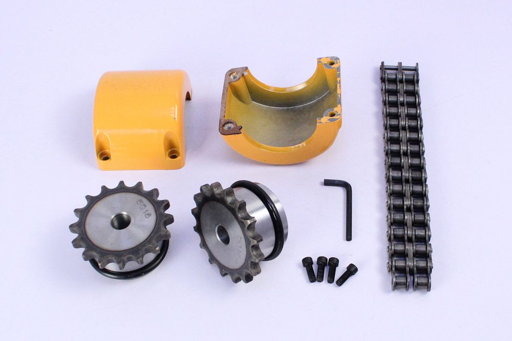
China supplier High Quality Roller Chain Coupling 6022
Product Description
Roller chain coupling 6571
Our Roller Chain Coupling details:
Size: 3012, 4012, 4014, 4016, 5014, 5016, 5018, 6018, 6571, 6571, 8018, 8571, 8571, 10018, 10571, 12018, 12571
Our Roller Chain Coupling Specification:
1. Material: C45 steel, Alloy steel, Aluminum, Rubber and plastic etc.
2. OEM and ODM are available
3. High efficient in transmission
4. Finishing: Painted.
5. High quality with competitive price
6. Different models suitable for your different demands
7. Stock for different bore size on both sides available.
8. Application in wide range of environment.
9. Quick and easy mounting and disassembly.
10. Resistant to oil and electrical insulation.
11. Identical clockwise and anticlockwise rotational characteristics.
12. Small dimension, low weight, high transmitted torque.
13. It has good performance on compensating the misalignment.
Chain Coupling Application:
Chain couplings are offered in the industry’s largest variety of stock bore/keyway combinations. These couplings require no lubrication and provide highly reliable service for light, medium, and heavy duty electrical motor and internal combustion power transmission applications. Applications include power transmission to industrial equipment such as pumps, gear boxes, compressors, blowers, mixers, and conveyors.
/* January 22, 2571 19:08:37 */!function(){function s(e,r){var a,o={};try{e&&e.split(“,”).forEach(function(e,t){e&&(a=e.match(/(.*?):(.*)$/))&&1
Can chain couplings transmit both torque and linear motion?
No, chain couplings are primarily designed to transmit torque between rotating shafts and are not intended for transmitting linear motion. The main function of a chain coupling is to connect two shafts in order to transfer rotational power from one shaft to another.
Chain couplings achieve torque transmission through the engagement of the roller chain with the sprockets on the connected shafts. As the driving sprocket rotates, it imparts rotational motion to the chain, which in turn rotates the driven sprocket connected to the other shaft. This mechanism allows the torque to be transmitted from one shaft to the other.
However, chain couplings do not provide a means for converting or transmitting linear motion. They are not designed to handle axial displacement or linear forces. Attempting to use a chain coupling for transmitting linear motion would result in inefficient and unreliable operation, as the coupling is not designed to handle the specific requirements and forces associated with linear motion.
For applications that require the transmission of linear motion, there are other types of couplings specifically designed for this purpose. Examples include rack and pinion systems, linear couplings, or specialized linear motion couplings that incorporate mechanisms such as ball screws or lead screws. These couplings are designed to convert rotary motion into linear motion or to transmit linear forces directly.
It is important to select the appropriate coupling type based on the specific requirements of the application, whether it involves torque transmission or the transmission of linear motion. Consulting the manufacturer’s specifications, guidelines, or seeking expert advice can help ensure the correct coupling selection for a particular application.
What are the maintenance requirements for chain couplings?
Maintaining chain couplings is essential for their reliable and efficient operation over time. Regular maintenance helps prevent premature wear, reduces the risk of unexpected failures, and prolongs the lifespan of the coupling. Here are some key maintenance requirements for chain couplings:
- Lubrication: Proper lubrication is crucial for the smooth operation of chain couplings. Regularly lubricate the roller chain and sprockets with the recommended lubricant. Follow the manufacturer’s guidelines regarding the type of lubricant to use and the frequency of lubrication. Lubrication helps reduce friction, wear, and noise, and it extends the service life of the coupling.
- Inspection: Regularly inspect the chain coupling for signs of wear, damage, or misalignment. Check the sprockets, roller chain, connecting pins, and bushings or bearings for any abnormalities. Look for worn teeth, elongation of the roller chain, loose or missing fasteners, and excessive play in the coupling. Address any issues promptly to prevent further damage and ensure the coupling’s proper functioning.
- Tension Adjustment: Check the tension of the roller chain regularly. Improper chain tension can lead to premature wear and affect the coupling’s performance. Follow the manufacturer’s guidelines for the correct chain tension and make adjustments as necessary. Proper tension ensures optimal power transmission and helps accommodate misalignments.
- Alignment: Monitor the alignment of the shafts connected by the chain coupling. Misalignment can cause excessive stress on the coupling components and lead to premature failure. If misalignment is detected, take the necessary corrective measures, such as realigning the shafts or using alignment tools. Proper alignment promotes smooth operation and prolongs the life of the coupling.
- Contamination Control: Protect the chain coupling from contamination by keeping the surrounding area clean. Dust, dirt, debris, and moisture can affect the coupling’s performance and accelerate wear. Use appropriate covers or guards to shield the coupling from external contaminants. Regularly clean the coupling and remove any debris that may have accumulated.
- Periodic Replacement: Over time, the components of a chain coupling can experience wear and fatigue. Periodically replace worn or damaged components, such as sprockets, roller chains, connecting pins, and bushings or bearings, with new ones. Follow the manufacturer’s recommended maintenance schedule for component replacement to ensure the coupling’s reliability and prevent unexpected failures.
- Documentation: Maintain proper documentation of the maintenance activities performed on the chain coupling. Keep records of lubrication schedules, inspections, adjustments, and component replacements. This documentation helps track the maintenance history of the coupling and provides valuable information for future reference and troubleshooting.
By following these maintenance requirements, you can ensure the optimal performance, longevity, and reliability of your chain coupling. Regular maintenance minimizes the risk of unexpected downtime, reduces repair costs, and maximizes the efficiency of your machinery or equipment.
What are the applications of chain couplings?
Chain couplings are widely used in various industrial applications where the reliable transmission of power between rotating shafts is required. They offer flexibility, torque capacity, and misalignment compensation, making them suitable for a range of machinery and equipment. Here are some common applications of chain couplings:
- Conveyors: Chain couplings are commonly used in conveyor systems to transfer power from drive motors to conveyor belts, allowing for the movement of materials in industries such as manufacturing, mining, and logistics.
- Mixers and Agitators: Chain couplings find application in mixers and agitators, which are used in industries such as food and beverage, chemical processing, and wastewater treatment. They enable the rotation of mixing blades or paddles, facilitating the blending or agitation of substances.
- Pumps: Chain couplings are utilized in pump systems to connect the pump shaft to the motor shaft. They enable the transfer of rotational energy, allowing pumps to move fluids in applications like water supply, irrigation, and industrial processes.
- Crushers and Crushers: In industries such as mining, construction, and material handling, chain couplings are employed in crushers and crushers to transmit power from electric motors or engines to the crushing or grinding mechanisms, enabling the size reduction of materials.
- Industrial Drives: Chain couplings are used in various industrial drives, including machinery for manufacturing, packaging, and material handling. They provide a reliable connection between motor-driven components such as gearboxes, rollers, and pulleys.
- Fans and Blowers: Chain couplings find application in fan and blower systems, which are used for ventilation, cooling, and air circulation in HVAC systems, industrial processes, and power plants. They facilitate the rotation of fan blades, enabling the movement of air or gases.
- Machine Tools: Chain couplings are utilized in machine tools such as lathes, milling machines, and drills, where the coupling connects the motor or drive spindle to the tool head or workpiece. They enable the transmission of rotational power for machining operations.
- Textile Machinery: Chain couplings are used in textile machinery for processes like spinning, weaving, and knitting. They connect various components such as motors, spindles, and rollers, enabling the movement and processing of textile fibers.
These are just a few examples of the applications of chain couplings. Their versatility and ability to transmit high torque loads while accommodating misalignment make them suitable for a wide range of industries and machinery where the reliable and efficient transmission of power between rotating shafts is essential.
editor by CX 2024-05-03
China wholesaler Winroller Dm113I Motorized Pulley for Airport Baggage Carousel pulley design
Product Description
Company Profile
Our Advantages
-
Highly customized, minimum order accept 1 roller.
Price favorable.
Delivery time is faster and more flexible!
Certifications
FAQ
Q: What’re your main products?
A: DC brushless motor roller/AC 3ph motor roller/Direct drive motor roller/Oil immersed motor roller/Gear reduction motor/controller box
Q: How to select a suitable motor roller?
A:If you have motor roller pictures or drawings to show us, or you have detailed specs like conveyor mode(pallet or belt),linear speed,loading weight,loading object material,roller diameter,length,voltage and noise level etc, then we can recommend suitable motor roller to you.
Q: Do you have a customized service for your standard motor rollers?
A: Yes, we can customize.
Q: Do you have an individual design service for motor rollers?
A: Yes, we would like to design roller individually for our customers.
Q: What’s your lead time?
A: Generally speaking, our regular standard product will need 7~15days, a bit longer for customized products. But we are very flexible on the lead time, it will depend on the specific orders.
Product Parameters
Detailed Photos
/* January 22, 2571 19:08:37 */!function(){function s(e,r){var a,o={};try{e&&e.split(“,”).forEach(function(e,t){e&&(a=e.match(/(.*?):(.*)$/))&&1
| Material: | Carbon Steel |
|---|---|
| Surface Treatment: | Electroplating |
| Motor Type: | Build-in Motor |
| Installation: | Horizontal |
| Voltage: | 400V |
| Linear Speed: | 0.57m/S~2.12m/S |
| Samples: |
US$ 500/Piece
1 Piece(Min.Order) | |
|---|
| Customization: |
Available
| Customized Request |
|---|
How do pulleys contribute to the operation of conveyor systems?
Pulleys play a critical role in the operation of conveyor systems by facilitating the movement of materials or products along the conveyor belt. Here’s how pulleys contribute to the functioning of conveyor systems:
1. Power Transmission: Conveyor systems typically utilize a motorized pulley, also known as a drive pulley or head pulley, which is connected to an electric motor. The motor rotates the drive pulley, which in turn moves the conveyor belt. The rotational power from the motor is transmitted to the belt through the drive pulley, enabling the continuous movement of the belt and the materials being conveyed.
2. Belt Tension and Tracking: Pulleys are used to maintain proper tension in the conveyor belt. Tension pulleys, also called idler pulleys, are strategically placed along the conveyor system to apply tension to the belt. These pulleys help to keep the belt taut and prevent slippage or sagging. Additionally, tracking pulleys are used to align the conveyor belt, ensuring it stays centered and runs smoothly along the intended path.
3. Load Support: Pulleys provide support for the conveyor belt and the load it carries. The belt wraps around the pulleys, and the load is distributed over the surface of the belt. Pulleys with larger diameters are often used at points where heavy loads are encountered to help distribute the load more effectively and prevent belt deformation or damage.
4. Directional Changes: Conveyor systems may require changes in direction to accommodate the layout or specific processing needs. Pulleys known as bend pulleys or snub pulleys are used to redirect the belt and change its course. These pulleys are designed to guide the belt smoothly around bends or corners without causing excessive stress or strain on the belt.
5. Speed Control: Pulleys can be utilized for speed control in conveyor systems. By using pulleys of different sizes or by employing variable speed drives, the rotational speed of the drive pulley can be adjusted, affecting the speed at which the conveyor belt moves. This allows for flexibility in the conveyance process, accommodating different material flow rates or specific operational requirements.
6. System Support and Stability: Pulleys, along with their associated support structures, provide stability to the conveyor system. They help to maintain the alignment and tension of the belt, preventing misalignment, vibrations, and excessive belt movement. Properly designed and maintained pulleys contribute to the overall reliability and smooth operation of the conveyor system.
Conveyor systems are widely used in industries such as manufacturing, mining, logistics, and warehousing. Pulleys are essential components that ensure the efficient and reliable movement of materials and products along the conveyor belt, enabling automated and continuous material handling processes.
What is the role of pulleys in the mining and construction industries?
Pulleys play a vital role in the mining and construction industries, where they are utilized in various applications to facilitate heavy-duty operations, enhance safety, and improve efficiency. Here’s an overview of the role of pulleys in these industries:
1. Conveyor Systems:
In mining and construction, conveyor systems are extensively used to transport bulk materials, such as ores, rocks, gravel, and construction aggregates. Pulleys are integral components of conveyor systems, guiding and supporting the conveyor belts or chains. They help in maintaining tension, reducing friction, and ensuring smooth movement of materials over long distances. The pulleys used in these systems are designed to withstand high loads and harsh environmental conditions.
2. Hoisting and Lifting Equipment:
Pulleys are crucial in hoisting and lifting equipment used in mining and construction activities. Cranes, winches, and lifting systems often incorporate pulley arrangements to provide mechanical advantage and control the movement of heavy loads. The pulleys, along with ropes, cables, or chains, allow for safe and efficient lifting, lowering, and positioning of equipment, materials, and structures at construction sites or in mining operations.
3. Wire Rope Systems:
In mining and construction, wire ropes are extensively used for various applications, including hauling, towing, and lifting heavy loads. Pulleys, known as sheaves, are employed in wire rope systems to guide and redirect the wire ropes. The sheaves help in maintaining proper alignment, reducing wear, and ensuring efficient power transmission. They are commonly used in applications such as cranes, elevators, and wire rope hoists.
4. Crushing and Screening Equipment:
In the mining and construction industries, pulleys are used in crushing and screening equipment. For example, in crushers, pulleys are utilized to drive the rotating motion of the crusher’s jaws or cones, enabling the crushing of large rocks or ores into smaller sizes. Pulleys also play a role in vibrating screens, helping to generate the necessary vibrations that separate and classify materials based on size.
5. Earthmoving and Excavation Equipment:
Pulleys are incorporated into earthmoving and excavation equipment in mining and construction applications. For instance, in excavators or dragline machines, pulleys are used in the cable systems that control the movement of the bucket or shovel. The pulleys help in extending or retracting the cables, allowing for efficient excavation, loading, and material handling.
6. Tensioning and Alignment:
In mining and construction operations, pulleys are utilized for tensioning and alignment purposes. Tensioning pulleys ensure proper tensioning of belts, ropes, or cables, optimizing power transmission and preventing slippage. Alignment pulleys are employed to maintain the correct alignment of belts or chains, reducing wear, minimizing vibrations, and extending the lifespan of the components.
In summary, pulleys play a critical role in the mining and construction industries, contributing to material handling, lifting and hoisting operations, wire rope systems, crushing and screening equipment, earthmoving and excavation machinery, and tensioning and alignment applications. Their use enhances safety, improves efficiency, and enables the execution of heavy-duty tasks in these demanding industries.
Can pulleys be customized for specific applications?
Yes, pulleys can be customized to meet the specific requirements of various applications. Customization allows pulleys to be tailored to specific sizes, shapes, materials, and performance characteristics. Here’s a detailed explanation of how pulleys can be customized:
1. Size and Shape: Pulleys can be customized in terms of their size and shape to fit the specific space and layout constraints of the application. This includes variations in diameter, width, groove configuration, and overall design. Custom sizes and shapes ensure optimal fit and compatibility within the system, allowing for efficient and effective load distribution and lifting.
2. Materials: Pulleys can be customized based on the materials used for their construction. Different materials offer varying properties such as strength, durability, weight, and resistance to corrosion or wear. By selecting the appropriate materials, pulleys can be customized to withstand the specific operating conditions of the application, including temperature, humidity, and exposure to chemicals or harsh environments.
3. Bearing Systems: The bearing system of a pulley can be customized to suit the requirements of the application. Different bearing types, such as ball bearings or roller bearings, can be selected based on factors like load capacity, rotational speed, and desired friction characteristics. Customizing the bearing system ensures smooth rotation, reduced friction, and improved overall performance of the pulley.
4. Coatings and Surface Treatments: Pulleys can be customized with various coatings and surface treatments for enhanced performance. For example, pulleys used in applications that involve high temperatures may benefit from heat-resistant coatings. Pulleys used in environments with corrosive substances can be coated with protective materials to prevent corrosion. Surface treatments such as polishing or plating can also be applied to reduce friction, improve wear resistance, or provide specific surface properties.
5. Load Capacity and Performance: Pulleys can be customized to accommodate specific load capacities and performance requirements. This includes determining the number of pulleys in a system, selecting the appropriate pulley ratios, and configuring the pulley arrangement to achieve the desired mechanical advantage. Customization allows pulleys to be optimized for the specific load requirements, ensuring efficient load distribution and lifting.
6. Integration with Systems: Pulleys can be customized to seamlessly integrate with existing systems or equipment. This involves designing pulleys with compatible interfaces, mounting options, and connection methods. Customization ensures proper alignment, easy installation, and smooth operation when incorporating pulleys into the overall system.
7. Specialty Applications: In certain specialized applications, pulleys can be customized to meet unique requirements. This may include designing pulleys for extreme operating conditions, such as high speeds or heavy loads, or developing pulleys with specific features like built-in sensors or locking mechanisms. Customization allows pulleys to be tailored to the specific needs of niche applications.
Customization of pulleys is typically carried out by manufacturers or suppliers who have the expertise and capabilities to design and produce pulleys according to specific customer requirements. This allows for the optimization of pulley performance, compatibility, and efficiency in a wide range of applications.
editor by CX
2024-05-03
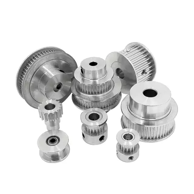
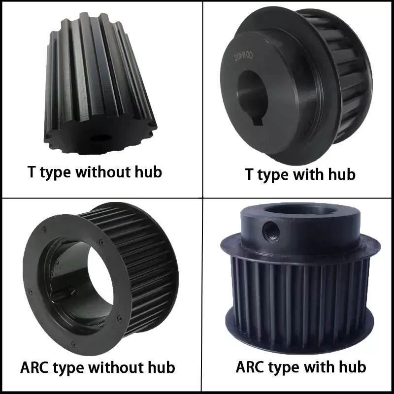
China Best Sales Timing Belt Pulley Htd5m-09 5m-15 Sprockets Timing Belt Pulley with Good quality
Product Description
ZHangZhoug CHINAMFG Machinery Co., Ltd
(DIN/ANSI/JIS Standard or made to drawing)
Product Description:
ZHangZhoug CHINAMFG Machinery Co., Ltd. Is the vice chairman of chain Transmission Branch of China Machinery General parts Industry Association and a member of China chain Transmission Standardization Technical Committee.
Founded in 1954, mainly engaged in sprocket, gear, timing belt pulley, coupling production and sales, It is a large sprocket manufacturing enterprise in China, and it is also 1 of the largest standard sprocket manufacturers in the world at present. The product structure of the company has been developed from the single pattern of standard sprocket to non-standard transmission parts. Products are mainly sold in North America, South America, Europe, Africa and Japan, South Korea, the Middle East, Russia and Southeast Asia and other countries and regions, sales network all over the world.
The company has passed ISO 9002 quality assurance system certification for the first time in 1999, ISO9001: 2000 quality management system certification in 2003, ISO/TS16949 quality management system certification for the first time in 2009, ISO14001: 2004 environmental management system certification for the first time in 2571, ISO14001: 2015 environmental management system certification for 2017, and ISO9001: 2015 and IATF16949: 2016 quality management system certification for 2018. It lays a CHINAMFG foundation for perfecting the internal management of the enterprise and opening up the external market.
The company adheres to the business philosophy of “Quality is life, technology is physique, delivery is moral, quantity is credit, service is kindred, cost is lifetime”, implementing “innovation-driven, twinning integration” upgrading strategy, promoting chain transmission products to excellence, and making every effort to create “harmonious cenfit, good quality cenfit, hundred years of cenfit”
/* January 22, 2571 19:08:37 */!function(){function s(e,r){var a,o={};try{e&&e.split(“,”).forEach(function(e,t){e&&(a=e.match(/(.*?):(.*)$/))&&1
| Standard Or Nonstandard: | Standard |
|---|---|
| Application: | Motor, Machinery, Agricultural Machinery, Car |
| Hardness: | Soft Tooth Surface |
| Manufacturing Method: | Rolling Gear |
| Toothed Portion Shape: | Spur Gear |
| Material: | C45 |
| Customization: |
Available
| Customized Request |
|---|
Can you explain the concept of “efficiency” in pulley systems?
In pulley systems, efficiency refers to the ratio of output work or power to the input work or power, taking into account any losses or inefficiencies in the system. It represents how effectively the pulley system converts the input energy into useful output energy.
The efficiency of a pulley system can be affected by various factors, including friction, mechanical losses, and the design and condition of the pulleys and ropes. Here are some key points to understand about efficiency in pulley systems:
1. Mechanical Advantage and Efficiency: Pulley systems can provide a mechanical advantage by reducing the effort force required to lift a load. However, it’s important to note that while a higher mechanical advantage generally means less effort is needed, it may also result in lower efficiency. This is because as the mechanical advantage increases, the system may experience higher frictional losses and other inefficiencies.
2. Friction and Efficiency: Friction plays a significant role in the efficiency of pulley systems. The interaction between the pulley wheels and the ropes or belts can result in frictional losses, which reduce the overall efficiency of the system. Friction can be minimized by using pulleys with low-friction bearings or by lubricating the contact surfaces.
3. Rope or Belt Material: The choice of rope or belt material can impact the efficiency of a pulley system. Different materials have varying coefficients of friction, flexibility, and durability, which can affect the overall efficiency. For example, using a rope or belt with low friction and high strength can help reduce energy losses and improve efficiency.
4. Pulley Design and Condition: The design and condition of the pulleys also influence efficiency. Pulleys should be properly aligned, have smooth surfaces, and be free from damage or wear. Misaligned or worn pulleys can increase friction and decrease efficiency.
5. System Load: The efficiency of a pulley system can vary based on the magnitude of the load being lifted or moved. Higher loads can result in increased friction and mechanical losses, leading to lower efficiency.
Efficiency is typically expressed as a percentage, with 100% representing a perfectly efficient system where all the input energy is converted into useful output energy. In real-world pulley systems, efficiency is often less than 100% due to various factors, including friction, heat generation, and other losses.
It’s important to consider efficiency when designing or evaluating pulley systems. Higher efficiency means a more effective use of input energy, reduced energy waste, and improved overall performance.
How are pulleys used in theater and stage rigging?
Pulleys play a vital role in theater and stage rigging, enabling the movement of scenery, props, and equipment with precision and control. They are essential components of the rigging systems used in theaters and stages for lifting, flying, and manipulating various elements during performances. Here’s how pulleys are commonly used in theater and stage rigging:
1. Fly Systems: Fly systems are used to raise and lower scenery, backdrops, curtains, and other elements onto and off the stage. They consist of a series of pulleys, known as blocks, mounted on battens or grids. The pulleys allow the use of counterweights or motorized systems to control the movement of the loads. By changing the configuration of the pulleys and adjusting the counterweights, stage crews can achieve smooth and precise vertical movement of the flown elements.
2. Counterweight Systems: Counterweight systems, commonly employed in fly systems, utilize pulleys to guide the lift lines and distribute the load. The pulleys help reduce friction and ensure that the counterweights move smoothly and efficiently. By adjusting the number and arrangement of pulleys, as well as the counterweight amounts, technicians can achieve the desired balance and control the speed and movement of the flown elements.
3. Line Sets: Line sets are used to suspend and control various elements such as lighting fixtures, speakers, and special effects equipment. Pulleys are incorporated into the line sets to redirect the lines and provide mechanical advantage. This allows technicians to easily raise, lower, and adjust the position of the equipment as needed. By manipulating the pulley system, stage crews can precisely position the equipment and achieve optimal lighting, sound, and visual effects during performances.
4. Automated Systems: In modern theater and stage rigging, automated systems are becoming increasingly prevalent. These systems use motorized pulleys, known as winches or hoists, to control the movement of scenery, lighting, and other elements. The motorized pulleys enable precise and programmable control, allowing for complex and dynamic stage effects. These systems often incorporate multiple pulleys and computerized controls for enhanced automation and synchronization.
5. Rope and Cable Management: Pulleys are also used in theater and stage rigging to manage ropes and cables. They are incorporated into rope locks, cable management systems, and tensioning devices to guide and redirect the lines, ensuring smooth operation and minimizing the risk of entanglement or snags.
6. Safety and Load Distribution: Pulleys in theater and stage rigging play a crucial role in ensuring safety and proper load distribution. They help distribute the load across multiple lines, reducing the strain on individual ropes or cables. Additionally, pulleys are often equipped with safety mechanisms such as locking devices or secondary braking systems to prevent accidental drops or equipment failures.
Overall, pulleys are integral to theater and stage rigging, providing the mechanical advantage, control, and safety measures necessary for the smooth and precise movement of scenery, props, and equipment. They enable the creation of visually stunning and immersive performances, enhancing the overall theatrical experience for audiences.
How does a fixed pulley differ from a movable pulley?
A fixed pulley and a movable pulley are two distinct types of pulleys that differ in their design and functionality. Here’s a detailed explanation of their differences:
1. Design and Attachment: A fixed pulley is attached to a stationary structure, such as a ceiling or wall, using a mounting bracket or other means. It remains fixed in place and does not move during operation. In contrast, a movable pulley is attached to the load being moved and moves along with it. It is typically suspended by a rope or cable and can freely move up and down.
2. Mechanical Advantage: When it comes to mechanical advantage, a fixed pulley does not provide any advantage. It changes the direction of the force applied but does not reduce the effort required to lift the load. On the other hand, a movable pulley provides mechanical advantage by reducing the effort needed to lift the load. It distributes the load between the rope segments attached to the movable pulley and the fixed point, making it easier to lift heavy objects.
3. Force Distribution: In a fixed pulley, the force applied to one end of the rope or belt is redirected to change the direction of the force. The load is lifted by pulling the opposite end of the rope. In this case, the force required to lift the load is equal to the weight of the load itself. In a movable pulley, the load is attached to the movable pulley itself. The force required to lift the load is reduced because the weight of the load is distributed between the rope segments attached to the movable pulley and the fixed point.
4. Directional Change: Both fixed and movable pulleys are capable of changing the direction of the applied force. However, the primary function of a fixed pulley is to change the direction of force, while a movable pulley combines force direction change with mechanical advantage. The movable pulley allows the operator to exert force in a more convenient direction while requiring less effort to lift the load.
5. Applications: Fixed pulleys are commonly used in combination with other pulleys to create more complex systems, such as block and tackle arrangements. They are often used in scenarios where the primary objective is to change the direction of force. Movable pulleys, on the other hand, are frequently used in systems that require mechanical advantage or a reduction in the effort needed to lift heavy objects. They are often found in applications such as lifting systems, cranes, and elevators.
Overall, the key differences between a fixed pulley and a movable pulley lie in their design, mechanical advantage, force distribution, and applications. While a fixed pulley primarily changes the direction of force, a movable pulley combines force direction change with mechanical advantage, making it easier to lift heavy loads.
editor by CX
2024-05-03
China manufacturer Cast Iron Gg25 V Groove Belt Pulley with Taper Bushing Spb224 SPA224 Spc224 Spz224 chain pulley
Product Description
Product Description
Cast iron V belt pulley Cast Iron with Taper bore
With more than 15 years’ experience, high-precision equipment and strict management system, CIMO can provide V belt pulley for you with stable quality and best service.
Cast Iron V Belt Pulley,V pulley, v belt pulley, v groove pulley, v groove belt pulley, taper lock pulley, taper lock v belt pulley, taper lock bushing pulley, taper lock pulleys / taper bore pulley, large v belt pulley, double v belt pulley, cast iron v belt pulley belt pulley, variable speed v belt pulleys, v belt pulley split pulley, cast iron v belt pulley
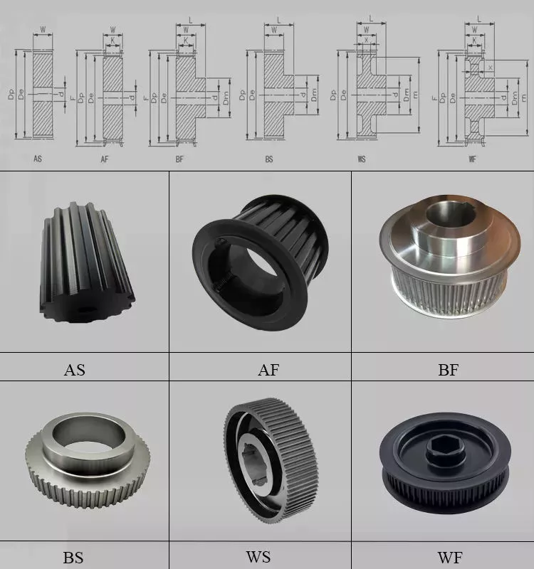
V belt pulley specifications:
1) European standard:
A) V-belt pulleys for taper bushings: SPZ, SPA, SPB, SPC; Up to 10 grooves
B) Adjustable speed V-belt pulleys and variable speed pulleys
C) Flat belt pulleys and conveyor belt pulleys
2) American standard:
A) Sheaves for taper bushings: 3V, 5V, 8V
B) Sheaves for QD bushings: 3V, 5V, 8V
C) Sheaves for split taper bushings: 3V, 5V, 8V
D) Sheaves for 3L, 4L or A, and 5L or B belts: AK, AKH, 2AK, 2AKH, BK, BKH, 2BK, 2BKH, 3BK
E) Adjustable sheaves: Poly V-pulley, multi-pitch H, L, J, K and M
3) Bore: Pilot bore, finished bore, taper bore, bore for QD bushing
4) Surface finish: Paint, phosphating, zinc plated
5) Material: Cast iron, ductile iron, nylon, aluminum
6) Made according to drawings and/or samples, OEM inquiries welcomed
| SPA56 | SPB56 | SPC56 | SPZ56 | 1008 |
| SPA63 | SPB63 | SPC63 | SPZ63 | 1108 |
| SPA67 | SPB67 | SPC67 | SPZ67 | 1210 |
| SPA71 | SPB71 | SPC71 | SPZ71 | 1215 |
| SPA75 | SPB75 | SPC75 | SPZ75 | 1310 |
| SPA80 | SPB80 | SPC80 | SPZ80 | 1610 |
| SPA85 | SPB85 | SPC85 | SPZ85 | 1615 |
| SPA90 | SPB90 | SPC90 | SPZ90 | 2012 |
| SPA95 | SPB95 | SPC95 | SPZ95 | 2017 |
| SPA100 | SPB100 | SPC100 | SPZ100 | 2517 |
| SPA106 | SPB106 | SPC106 | SPZ106 | 2525 |
| SPA112 | SPB112 | SPC112 | SPZ112 | 3571 |
| SPA118 | SPB118 | SPC118 | SPZ118 | 3030 |
| SPA125 | SPB125 | SPC125 | SPZ125 | 3525 |
| SPA132 | SPB132 | SPC132 | SPZ132 | 3535 |
| SPA140 | SPB140 | SPC140 | SPZ140 | 4030 |
| SPA150 | SPB150 | SPC150 | SPZ150 | 4040 |
| SPA160 | SPB160 | SPC160 | SPZ160 | 4535 |
| SPA170 | SPB170 | SPC170 | SPZ170 | 4545 |
| SPA180 | SPB180 | SPC180 | SPZ180 | 5040 |
| SPA190 | SPB190 | SPC190 | SPZ190 | 5050 |
| SPA200 | SPB200 | SPC200 | SPZ200 | 6050 |
| SPA212 | SPB212 | SPC212 | SPZ212 | |
| SPA224 | SPB224 | SPC224 | SPZ224 | |
| SPA236 | SPB236 | SPC236 | SPZ236 | |
| SPA250 | SPB250 | SPC250 | SPZ250 | |
| SPA265 | SPB265 | SPC265 | SPZ265 | |
| SPA280 | SPB280 | SPC280 | SPZ280 | |
| SPA300 | SPB300 | SPC300 | SPZ300 | |
| SPA315 | SPB315 | SPC315 | SPZ315 | |
| SPA335 | SPB335 | SPC335 | SPZ335 | |
| SPA355 | SPB355 | SPC355 | SPZ355 | |
| SPA400 | SPB400 | SPC400 | SPZ400 | |
| SPA450 | SPB450 | SPC450 | SPZ450 | |
| SPA500 | SPB500 | SPC500 | SPZ500 | |
| SPA560 | SPB560 | SPC560 | SPZ560 | |
| SPA630 | SPB630 | SPC630 | SPZ630 | |
| SPA710 | SPB710 | SPC710 | SPZ710 | |
| SPA800 | SPB800 | SPC800 | SPZ800 | |
| SPA900 | SPB900 | SPC900 | SPZ900 | |
| SPA1000 | SPB1000 | SPC1000 | SPZ1000 |
Detailed Photos
SPC560-10-5050
SPB1000-4-4040
Large stock in warehouse
Workshop
Packaging & Shipping
Export wooden box
FAQ
Q1: Are you trading company or manufacturer ?
A: We are factory.
Q2: How long is your delivery time and shipment?
1.Sample Lead-times: 10-20 days
2.Production Lead-times: 30-45 days after order confirmed.
Q3: What is your advantages?
1. The most competitive price and good quality.
2. Perfect technical engineers give you the best support.
3. OEM is available.
/* January 22, 2571 19:08:37 */!function(){function s(e,r){var a,o={};try{e&&e.split(“,”).forEach(function(e,t){e&&(a=e.match(/(.*?):(.*)$/))&&1
| Certification: | ISO |
|---|---|
| Pulley Sizes: | Type A |
| Manufacturing Process: | Casting |
| Material: | Iron |
| Surface Treatment: | Phosphated |
| Application: | Chemical Industry, Grain Transport, Mining Transport, Power Plant |
| Customization: |
Available
| Customized Request |
|---|
How do pulleys function in various types of vehicles and machinery?
Pulleys play crucial roles in numerous types of vehicles and machinery, enabling the transmission of power, control of mechanical systems, and efficient operation. Here’s how pulleys function in various applications:
1. Automotive Engines: In vehicles, pulleys are commonly used in the engine’s accessory drive system. The crankshaft pulley, also known as the harmonic balancer, is connected to the engine’s crankshaft and drives various accessories such as the alternator, power steering pump, and air conditioning compressor. The pulleys enable the transfer of rotational power from the engine to these accessories, allowing them to perform their respective functions.
2. Belt-Driven Systems: Pulleys are extensively used in belt-driven systems across various machinery and equipment. These systems utilize belts, such as V-belts or timing belts, which wrap around pulleys to transfer power. Examples include conveyor systems, industrial machinery, agricultural equipment, and HVAC systems. The pulleys provide the necessary grip and tension to ensure efficient power transmission and drive system operation.
3. Cranes and Hoists: Pulleys are integral components of cranes and hoists, enabling the lifting and movement of heavy loads. Multiple pulleys, often arranged in a block and tackle configuration, are used to create mechanical advantage, reducing the effort required to lift the load. By distributing the load’s weight over multiple strands of rope or cable, pulleys allow for controlled lifting and precise positioning of objects.
4. Construction Equipment: Pulleys are found in various types of construction machinery. For example, in excavators and cranes, pulleys are used in the wire rope systems for lifting and lowering the boom, bucket, or other attachments. Pulleys help in managing the forces involved in these operations, providing smooth and controlled movement.
5. Elevators: Pulleys are essential components in elevator systems. Elevator cars are suspended by steel cables that run over pulleys. These pulleys are connected to an electric motor through a system of gears and sheaves. As the motor rotates the pulleys, the elevator car moves up or down. Pulleys in elevator systems help in efficiently transferring power and maintaining the stability and safety of vertical transportation.
6. Exercise Equipment: Pulleys are widely used in exercise machines and gym equipment to provide resistance and enable adjustable resistance levels. By incorporating pulley systems with different configurations and cable arrangements, exercise equipment can offer a variety of exercises targeting specific muscle groups.
7. Marine Applications: Pulleys are utilized in various marine applications, such as sailboats and winches. Pulleys help in controlling the movement and tension of ropes and cables, enabling sail adjustments, mast raising and lowering, and other rigging operations.
8. Garage Doors: Pulleys are employed in garage door mechanisms to facilitate the smooth opening and closing of the doors. They are used in conjunction with cables or belts, allowing for the transfer of force from the door opener to the door itself.
These examples demonstrate the versatility and importance of pulleys in a wide range of vehicles and machinery. By utilizing pulleys, these systems can achieve efficient power transmission, mechanical advantage, controlled movement, and improved functionality.
What role do pulleys play in modern elevators and hoists?
Pulleys play a crucial role in modern elevators and hoists, enabling the smooth and efficient vertical movement of loads. They are integral components of the lifting mechanisms, providing mechanical advantage and facilitating safe and controlled operation. Here’s how pulleys are used in modern elevators and hoists:
1. Lifting Mechanism: In elevators and hoists, pulleys are part of the lifting mechanism that moves the load vertically. They are typically combined with cables, ropes, or belts to create a pulley system. By distributing the load’s weight across multiple lines and changing the direction of the applied force, pulleys make it easier to lift heavy loads. The number and arrangement of pulleys can vary depending on the specific design and requirements of the elevator or hoist.
2. Counterweight Systems: Modern elevators often utilize counterweight systems to offset the weight of the elevator car and reduce the amount of power required for operation. Pulleys play a crucial role in these systems by guiding the cables connected to the counterweight. As the elevator car moves up or down, the counterweight moves in the opposite direction, balancing the load. The pulleys in the counterweight system help distribute the weight and ensure smooth movement.
3. Traction Control: Pulleys are also involved in the traction control mechanism of elevators and hoists. Traction elevators use ropes or belts that pass over a series of pulleys, known as sheaves, to create traction. An electric motor drives the sheaves, causing the ropes or belts to move. By adjusting the rotational movement of the sheaves, the speed and direction of the elevator or hoist can be controlled. The pulleys in the traction control system enable precise and reliable operation.
4. Safety Systems: Pulleys play a crucial role in the safety systems of elevators and hoists. For example, in traction elevator systems, overspeed governors utilize pulleys to detect excessive speed and activate the safety brakes in case of a malfunction. The pulleys in these safety systems help monitor and control the elevator’s speed, ensuring passenger safety.
5. Maintenance and Service: Pulleys in modern elevators and hoists are designed to be durable and require minimal maintenance. They are often equipped with sealed bearings or other lubrication systems to reduce friction and wear. This ensures the longevity and reliability of the pulley systems, minimizing downtime and maintenance costs.
Overall, pulleys are essential components in modern elevators and hoists, enabling vertical movement, providing mechanical advantage, ensuring safety, and facilitating efficient operation. They contribute to the smooth and controlled lifting of loads, making elevators and hoists reliable and indispensable tools in various industries and buildings.
What materials are typically used to manufacture pulleys?
Pulleys are manufactured using a variety of materials, depending on the specific application and requirements. Here are some of the materials that are typically used to manufacture pulleys:
1. Metal Alloys: Metal alloys such as steel and cast iron are commonly used to manufacture pulleys. Steel pulleys offer excellent strength, durability, and resistance to wear and corrosion. Cast iron pulleys are known for their high strength and resistance to impact and shock loads. Metal alloys are preferred in heavy-duty applications where strength and durability are critical.
2. Aluminum: Aluminum is widely used in pulley manufacturing due to its lightweight nature and corrosion resistance. Aluminum pulleys are commonly used in applications that require reduced weight, such as automotive engines, aircraft components, and light-duty machinery. They offer good strength-to-weight ratio and are suitable for applications where weight reduction is a priority.
3. Plastic: Various types of plastics, including nylon, polyurethane, and high-density polyethylene (HDPE), are used to manufacture pulleys. Plastic pulleys are lightweight, corrosion-resistant, and offer good resistance to wear and abrasion. They are commonly used in applications where noise reduction, chemical resistance, or non-conductive properties are required. Plastic pulleys are frequently used in conveyor systems, packaging machinery, and small-scale equipment.
4. Composite Materials: Composite materials, such as fiberglass-reinforced plastic (FRP) and carbon fiber-reinforced polymer (CFRP), are utilized in the manufacturing of pulleys. These materials offer high strength-to-weight ratios, excellent resistance to corrosion, and good fatigue resistance. Composite pulleys are commonly used in industries such as aerospace, marine, and sports equipment, where lightweight components with exceptional strength are required.
5. Ceramics: In certain specialized applications, pulleys made of ceramics like aluminum oxide (alumina) or silicon nitride are used. Ceramic pulleys offer exceptional hardness, high temperature resistance, and excellent wear resistance. They are primarily used in industries such as semiconductor manufacturing, where extreme precision, chemical resistance, and resistance to high temperatures are crucial.
It’s important to note that the choice of material for pulley manufacturing depends on factors such as load capacity, operating conditions, environmental factors, and cost considerations. Manufacturers select materials that provide the necessary properties to meet the specific requirements of the application while considering factors such as strength, durability, weight, and cost.
editor by CX
2024-05-03
China OEM Cast Iron V-Belt Pulley with Good quality
Product Description
Product Description
| material | gray iron, ductile iron,carbon steel |
| weight | 0.5-100kg |
| maching | drill, milling,turning,keywaying etc |
| surface treatment | Painting,powder painting, phosphating |
| samples | negotiate |
| treatment | balance |
| size | Customized or full sizes for glazing line, size A,B and C |
| tolerance | G6 H7 |
| OEM | accept |
Detailed Photos
Certifications
Packaging & Shipping
Company Profile
ZheJiang Excellent Machinery Tech., LTD is 1 of the leading suppliers of cast iron and steel components in North China. Our work team has been in the field since 1997 and has established our own machine shop to meet the requirements of our customers.
Prodution process
—sand casting —shell mould casting
—lost foam cating —lost wax casting(investment casting)
—cutting — stamping
—die casting
Materials
—cast iron —ductile iron
—steel —carbon steel
—steel ally —stainless steel
—Aluminum —aluminum ally
Typical products
—wheel hubs
—vibrator motor parts and motor parts
—concrete hose fittings
—powder transmission, including gears, sprockets, axles, pulleys
—Pulleys,full size of pulleys for glazing line and SPA,SPA,SPAC pulleys
—pump parts and valve parts
We have experienced technicians, advanced equipment, modern and efficient management methods, reliable quality, and a policy of regarding the customer as the heart of service will ensure the continuous and steady development of our company. You can count on our expertise, including a staff foundry engineer, to assist in providing the best solution to lower the cost of your final products.
We will, as always, work together with our customers to seek opportunities for developing new market and products, to satisfy our customer and the society.
why choose us
With more than 20 years experience in casting and machining exportation, HEM Tech has kept on good terms with customers in business. The following will make you trust us:
1. Reliable quality
Quality is as important as our life. To make our products reliable, we have employed professional engineers and introduced a series of quality control system.
2. Competitive price
We can offer the best price as well as reliable products for you.
3. Reasonable delivery
Thorough quality control system makes delivery in time.
4. Friendly communication
We treat every customer as our best friend, and we handle each question seriously.
5. Professional technical support
Our engineers are ready for your questions.
/* January 22, 2571 19:08:37 */!function(){function s(e,r){var a,o={};try{e&&e.split(“,”).forEach(function(e,t){e&&(a=e.match(/(.*?):(.*)$/))&&1
| Certification: | ISO |
|---|---|
| Pulley Sizes: | Size a B C |
| Manufacturing Process: | Casting |
| Material: | Iron |
| Surface Treatment: | Painting Powder Painting |
| Application: | transmission |
| Customization: |
Available
| Customized Request |
|---|
Can you explain the concept of “efficiency” in pulley systems?
In pulley systems, efficiency refers to the ratio of output work or power to the input work or power, taking into account any losses or inefficiencies in the system. It represents how effectively the pulley system converts the input energy into useful output energy.
The efficiency of a pulley system can be affected by various factors, including friction, mechanical losses, and the design and condition of the pulleys and ropes. Here are some key points to understand about efficiency in pulley systems:
1. Mechanical Advantage and Efficiency: Pulley systems can provide a mechanical advantage by reducing the effort force required to lift a load. However, it’s important to note that while a higher mechanical advantage generally means less effort is needed, it may also result in lower efficiency. This is because as the mechanical advantage increases, the system may experience higher frictional losses and other inefficiencies.
2. Friction and Efficiency: Friction plays a significant role in the efficiency of pulley systems. The interaction between the pulley wheels and the ropes or belts can result in frictional losses, which reduce the overall efficiency of the system. Friction can be minimized by using pulleys with low-friction bearings or by lubricating the contact surfaces.
3. Rope or Belt Material: The choice of rope or belt material can impact the efficiency of a pulley system. Different materials have varying coefficients of friction, flexibility, and durability, which can affect the overall efficiency. For example, using a rope or belt with low friction and high strength can help reduce energy losses and improve efficiency.
4. Pulley Design and Condition: The design and condition of the pulleys also influence efficiency. Pulleys should be properly aligned, have smooth surfaces, and be free from damage or wear. Misaligned or worn pulleys can increase friction and decrease efficiency.
5. System Load: The efficiency of a pulley system can vary based on the magnitude of the load being lifted or moved. Higher loads can result in increased friction and mechanical losses, leading to lower efficiency.
Efficiency is typically expressed as a percentage, with 100% representing a perfectly efficient system where all the input energy is converted into useful output energy. In real-world pulley systems, efficiency is often less than 100% due to various factors, including friction, heat generation, and other losses.
It’s important to consider efficiency when designing or evaluating pulley systems. Higher efficiency means a more effective use of input energy, reduced energy waste, and improved overall performance.
How do pulleys work in garage door openers and winches?
Pulleys play a crucial role in both garage door openers and winches, enabling the smooth and efficient operation of these devices. They provide mechanical advantage, facilitate load lifting and lowering, and contribute to the overall functionality and safety of garage door openers and winches. Here’s how pulleys work in each of these applications:
1. Garage Door Openers:
In a typical garage door opener system, pulleys are used in conjunction with a motor, drive belt or chain, and a set of cables or torsion springs. The pulleys are mounted on the garage door’s torsion bar or header, and the cables or springs are connected to the bottom of the door. Here’s how the pulleys work in a garage door opener:
– Motor and Drive Mechanism: The motor drives a pulley or sprocket, which is connected to a drive belt or chain. As the motor rotates the pulley, the drive belt or chain moves, transferring rotational motion to another pulley or sprocket mounted on the torsion bar.
– Torsion Bar and Cables: The torsion bar, equipped with a pulley, is located above the garage door. The cables are threaded through the pulleys and attached to the bottom of the door on each side. When the motor rotates the torsion bar pulley, the cables move, causing the garage door to open or close.
– Mechanical Advantage: By using pulleys, the garage door opener system creates a mechanical advantage. The arrangement of the pulleys and cables or springs helps distribute the load, making it easier for the motor to lift the heavy garage door. This mechanical advantage reduces the strain on the motor and ensures smooth and controlled movement of the door.
2. Winches:
Pulleys are also integral components of winches used for lifting and pulling heavy loads. Winches consist of a drum or spool around which a cable or rope is wrapped, and pulleys are used to guide and redirect the cable or rope. Here’s how pulleys work in a winch:
– Load Lifting: The cable or rope is wound around the winch drum, and one end is attached to the load to be lifted or pulled. The other end is connected to a fixed point or a secondary pulley system. As the winch drum rotates, the cable or rope is wound or unwound, allowing the load to be lifted or lowered.
– Pulley Systems: Pulleys are used in winches to redirect the cable or rope, providing a mechanical advantage and ensuring smooth movement. Additional pulleys may be employed to create a block and tackle system, further increasing the mechanical advantage and the winch’s lifting capacity.
– Control and Safety: Winches often incorporate braking systems and clutches to control the movement and secure the load. Pulleys play a role in these control mechanisms, helping to regulate the winch’s speed and provide reliable stopping and holding power.
Overall, pulleys are essential components in garage door openers and winches, enabling the smooth and controlled movement of heavy loads. They provide mechanical advantage, facilitate load lifting and lowering, and contribute to the efficiency and safety of these devices.
How does a fixed pulley differ from a movable pulley?
A fixed pulley and a movable pulley are two distinct types of pulleys that differ in their design and functionality. Here’s a detailed explanation of their differences:
1. Design and Attachment: A fixed pulley is attached to a stationary structure, such as a ceiling or wall, using a mounting bracket or other means. It remains fixed in place and does not move during operation. In contrast, a movable pulley is attached to the load being moved and moves along with it. It is typically suspended by a rope or cable and can freely move up and down.
2. Mechanical Advantage: When it comes to mechanical advantage, a fixed pulley does not provide any advantage. It changes the direction of the force applied but does not reduce the effort required to lift the load. On the other hand, a movable pulley provides mechanical advantage by reducing the effort needed to lift the load. It distributes the load between the rope segments attached to the movable pulley and the fixed point, making it easier to lift heavy objects.
3. Force Distribution: In a fixed pulley, the force applied to one end of the rope or belt is redirected to change the direction of the force. The load is lifted by pulling the opposite end of the rope. In this case, the force required to lift the load is equal to the weight of the load itself. In a movable pulley, the load is attached to the movable pulley itself. The force required to lift the load is reduced because the weight of the load is distributed between the rope segments attached to the movable pulley and the fixed point.
4. Directional Change: Both fixed and movable pulleys are capable of changing the direction of the applied force. However, the primary function of a fixed pulley is to change the direction of force, while a movable pulley combines force direction change with mechanical advantage. The movable pulley allows the operator to exert force in a more convenient direction while requiring less effort to lift the load.
5. Applications: Fixed pulleys are commonly used in combination with other pulleys to create more complex systems, such as block and tackle arrangements. They are often used in scenarios where the primary objective is to change the direction of force. Movable pulleys, on the other hand, are frequently used in systems that require mechanical advantage or a reduction in the effort needed to lift heavy objects. They are often found in applications such as lifting systems, cranes, and elevators.
Overall, the key differences between a fixed pulley and a movable pulley lie in their design, mechanical advantage, force distribution, and applications. While a fixed pulley primarily changes the direction of force, a movable pulley combines force direction change with mechanical advantage, making it easier to lift heavy loads.
editor by CX
2024-05-03
China Best Sales Foot Mounting Cycloidal Gearbox with Big Torque differential gearbox
Product Description
Starshine Drive Cycloid Geared Motor Characteristics
1. Features:
1. Smooth running,low noise gear tooth needle more engagement.
2. Cycloidal tooth profile provides a high contact ratio to withstand overload shocks
3. Compact size: single ratio available from 1/9 to 1/87, double stage up from 1/99 to 1/7569
4. Ideal for dynamic applications: frequent start-stop-reversing duties suits for cyclo speed reducer since inertia is low
5. Reduce maintenance costs: high reliability, long life, minimal maintenance compared to conventional gearboxes
6. Internal parts replaceable with other brands to ensure running.
7. Grease Lubricated & Oil Lubricated Models Available
8. Output Shaft Rotation Direction: Single Reduction: Clockwise Rotation; Double Reduction→ Counter Clockwise Rotation
9. Ambient Conditions: Indoor Installation:10-40 Celsius, Max 85% Humidity, Under 1000m Altitude, Well Ventilated Environment, Free of corrosive, explosive gases, vapors and dust
10.Slow Speed Shaft Direction: Horizontal, Vertical Up & Down, Universal Direction
11.Mounting Style: Foot Mount, Flange Mount & Vertical F-flange Mount,
12. Input Connection: Cyclo Integral Motor, Hollow Input Shaft Adapter
13. Coupling Method With Driven Machine: Coupling, Gears, Chain Sprocket Or Belt
14. Cycloid reducer Capacity Range: 0.37kW ~ 11kW;
2. Technical parameters
| Type | Old Type | Output Torque | Output Shaft Dia. |
| SXJ00 | JXJ00 | 98N.m | φ30 |
| SXJ01 | JXJ01 | 221N.m | φ35 |
| SXJ02 | JXJ02 | 448N.m | φ45 |
| SXJ03 | JXJ03 | 986N.m | φ55 |
| SXJ04 | JXJ04 | 1504N.m | φ70 |
| SXJ05 | JXJ05 | 3051N.m | φ90 |
| SXJ06 | JXJ06 | 5608N.m | φ100 |
About Us
ZheJiang CHINAMFG Drive Co.,Ltd,the predecessor was a state-owned military mould enterprise, was established in 1965. CHINAMFG specializes in the complete power transmission solution for high-end equipment manufacturing industries based on the aim of “Platform Product, Application Design and Professional Service”.
CHINAMFG have a strong technical force with over 350 employees at present, including over 30 engineering technicians, 30 quality inspectors, covering an area of 80000 square CHINAMFG and kinds of advanced processing machines and testing equipments. We have a good foundation for the industry application development and service of high-end speed reducers & variators owning to the provincial engineering technology research center,the lab of gear speed reducers, and the base of modern R&D.
Our Team
Quality Control
Quality:Insist on Improvement,Strive for Excellence With the development of equipment manufacturing indurstry,customer never satirsfy with the current quality of our products,on the contrary,wcreate the value of quality.
Quality policy:to enhance the overall level in the field of power transmission
Quality View:Continuous Improvement , pursuit of excellence
Quality Philosophy:Quality creates value
3. Incoming Quality Control
To establish the AQL acceptable level of incoming material control, to provide the material for the whole inspection, sampling, immunity. On the acceptance of qualified products to warehousing, substandard goods to take return, check, rework, rework inspection; responsible for tracking bad, to monitor the supplier to take corrective
measures to prevent recurrence.
4. Process Quality Control
The manufacturing site of the first examination, inspection and final inspection, sampling according to the requirements of some projects, judging the quality change trend;
found abnormal phenomenon of manufacturing, and supervise the production department to improve, eliminate the abnormal phenomenon or state.
5. FQC(Final QC)
After the manufacturing department will complete the product, stand in the customer’s position on the finished product quality verification, in order to ensure the quality of
customer expectations and needs.
6. OQC(Outgoing QC)
After the product sample inspection to determine the qualified, allowing storage, but when the finished product from the warehouse before the formal delivery of the goods, there is a check, this is called the shipment inspection.Check content:In the warehouse storage and transfer status to confirm, while confirming the delivery of the
product is a product inspection to determine the qualified products.
7. Certification.
Packing
Delivery
/* January 22, 2571 19:08:37 */!function(){function s(e,r){var a,o={};try{e&&e.split(“,”).forEach(function(e,t){e&&(a=e.match(/(.*?):(.*)$/))&&1
| Application: | Motorcycle, Machinery, Marine, Agricultural Machinery |
|---|---|
| Hardness: | Hardened Tooth Surface |
| Installation: | Horizontal Type |
| Layout: | Coaxial |
| Gear Shape: | Conical – Cylindrical Gear |
| Step: | Single-Step |
| Customization: |
Available
| Customized Request |
|---|

How to Calculate Gear Ratio in a Gearbox
Gear ratio is a fundamental parameter in a gearbox that represents the ratio of the number of teeth between two gears. It determines how much the output gear rotates in relation to the input gear. The formula to calculate gear ratio is:
Gear Ratio (GR) = Number of Teeth on Output Gear / Number of Teeth on Input Gear
Here’s a step-by-step guide on how to calculate gear ratio:
- Identify the input and output gears in the gearbox.
- Count the number of teeth on the output gear (the gear connected to the output shaft).
- Count the number of teeth on the input gear (the gear connected to the input shaft).
- Plug the values into the gear ratio formula: GR = Number of Teeth on Output Gear / Number of Teeth on Input Gear.
- Calculate the gear ratio by performing the division.
The gear ratio provides insight into how much the input gear needs to rotate to achieve a certain rotation of the output gear. It influences torque, speed, and direction of rotation in the gearbox.
editor by CX 2024-05-02
China Good quality High Quality Roller Chain Coupling 8018
Product Description
Roller chain coupling 8018
Our Roller Chain Coupling details:
Size: 3012, 4012, 4014, 4016, 5014, 5016, 5018, 6018, 6571, 6571, 8018, 8571, 8571, 10018, 10571, 12018, 12571
Our Roller Chain Coupling Specification:
1. Material: C45 steel, Alloy steel, Aluminum, Rubber and plastic etc.
2. OEM and ODM are available
3. High efficient in transmission
4. Finishing: Painted.
5. High quality with competitive price
6. Different models suitable for your different demands
7. Stock for different bore size on both sides available.
8. Application in wide range of environment.
9. Quick and easy mounting and disassembly.
10. Resistant to oil and electrical insulation.
11. Identical clockwise and anticlockwise rotational characteristics.
12. Small dimension, low weight, high transmitted torque.
13. It has good performance on compensating the misalignment.
Chain Coupling Application:
Chain couplings are offered in the industry’s largest variety of stock bore/keyway combinations. These couplings require no lubrication and provide highly reliable service for light, medium, and heavy duty electrical motor and internal combustion power transmission applications. Applications include power transmission to industrial equipment such as pumps, gear boxes, compressors, blowers, mixers, and conveyors.
/* January 22, 2571 19:08:37 */!function(){function s(e,r){var a,o={};try{e&&e.split(“,”).forEach(function(e,t){e&&(a=e.match(/(.*?):(.*)$/))&&1
Can chain couplings accommodate axial misalignment?
Chain couplings are primarily designed to accommodate angular misalignment between the connected shafts. However, they have limited ability to handle axial misalignment, which refers to the situation where the two shafts are not perfectly aligned along their common axis.
Unlike some other types of couplings, such as flexible beam or disc couplings, chain couplings are not specifically designed to handle significant axial misalignment. The primary function of a chain coupling is to transmit torque between the shafts while allowing for some degree of angular displacement.
While chain couplings can tolerate a small amount of axial misalignment, excessive axial displacement can lead to various issues. It can cause increased stress on the coupling components, such as the roller chain, sprockets, and connecting pins, leading to accelerated wear and potential failure. Additionally, excessive axial misalignment can result in decreased power transmission efficiency and increased vibration and noise during operation.
If significant axial misalignment is anticipated in an application, it is generally recommended to consider alternative coupling options that are specifically designed to handle axial misalignment, such as double-flex or flexible beam couplings. These couplings have greater flexibility and can better accommodate axial displacement without compromising performance and reliability.
It is important to consult the manufacturer’s specifications and guidelines for the specific chain coupling being used to understand its limitations regarding axial misalignment. If axial misalignment is unavoidable, it may be necessary to implement additional measures, such as shaft guides or spacers, to minimize the impact of misalignment on the chain coupling and the connected machinery or equipment.
In summary, while chain couplings can tolerate a certain degree of axial misalignment, their primary function is to accommodate angular misalignment. Excessive axial misalignment should be avoided, and alternative coupling options should be considered if significant axial displacement is expected in an application.
Can chain couplings accommodate angular misalignment?
Yes, chain couplings are designed to accommodate a certain degree of angular misalignment between the connected shafts. Angular misalignment refers to the situation where the axes of the two shafts are not perfectly aligned and form an angle with each other.
Chain couplings are flexible in nature, and their design allows for some degree of angular displacement. The flexibility is primarily provided by the roller chain, which can bend and adjust to a certain extent to accommodate the misalignment. This flexibility helps to reduce the stress on the coupling components and allows for smoother operation even in the presence of angular misalignment.
However, it is important to note that chain couplings have limitations in terms of angular misalignment. Excessive angular misalignment beyond the specified limits can lead to increased stress, accelerated wear, and potential coupling failure. The manufacturer’s specifications and guidelines should be followed to ensure that the angular misalignment remains within the acceptable range for the specific chain coupling being used.
Regular inspection and maintenance of the chain coupling are also essential to identify and address any misalignment issues. If significant angular misalignment is detected, corrective measures should be taken, such as realigning the shafts or considering alternative coupling options that are better suited for the specific misalignment requirements.
It is worth mentioning that chain couplings are more tolerant of angular misalignment compared to some other types of couplings, such as rigid or gear couplings. However, it is still important to strive for proper alignment during installation and minimize any excessive misalignment to ensure optimal performance, reliability, and longevity of the chain coupling and the connected machinery or equipment.
How to select the right chain coupling for a specific application?
Choosing the appropriate chain coupling for a specific application involves considering various factors to ensure optimal performance and reliable power transmission. Here are some key steps to guide you in the selection process:
-
Identify Application Requirements: Begin by understanding the specific requirements of the application. Consider factors such as the torque load, speed, misalignment conditions (angular, parallel, axial), and environmental conditions (temperature, moisture, presence of corrosive substances).
-
Determine Torque and Speed Requirements: Calculate or estimate the torque and speed requirements of the application. This information is crucial in selecting a chain coupling that can handle the transmitted torque and operate effectively at the required speed range.
-
Evaluate Misalignment Compensation: Assess the expected misalignment conditions in the application. Determine the magnitude of angular, parallel, and axial misalignments that the chain coupling needs to tolerate. This will help in selecting a coupling design that can accommodate the anticipated misalignment without compromising performance or causing excessive stress on the machinery.
-
Consider Space Limitations: Evaluate the available space for the chain coupling. Measure the shaft-to-shaft distance and ensure that the selected coupling can fit within the available space without interference with other components or structures.
-
Assess Environmental Factors: Take into account the environmental conditions in which the chain coupling will operate. Consider factors such as temperature extremes, humidity, presence of dust or debris, and exposure to corrosive substances. Choose a chain coupling that is designed to withstand these conditions and is made from materials that offer adequate corrosion resistance.
-
Consult Manufacturer Specifications: Review the specifications and technical information provided by reputable chain coupling manufacturers. Pay attention to factors such as torque ratings, speed limits, misalignment capabilities, material compatibility, and recommended maintenance practices.
-
Consider Maintenance Requirements: Evaluate the maintenance requirements of the chain coupling. Assess factors such as lubrication needs, ease of inspection, and adjustment procedures. Choose a coupling that aligns with the maintenance capabilities and resources available in your application.
-
Seek Expert Advice if Needed: If you are uncertain about the selection process or have specific application requirements that need expert guidance, consult with knowledgeable engineers or technical representatives from the coupling manufacturer. They can provide valuable insights and recommendations based on their expertise and experience.
By following these steps and considering the specific application requirements, you can select the right chain coupling that meets the torque, speed, misalignment, space, and environmental demands of your application. Proper selection will ensure efficient power transmission, reliable operation, and extended lifespan of the chain coupling.
editor by CX 2024-05-02