Product Description
Medium High Speed Advance Marine Gearbox For Ship Traffic Boat Passenger Ship Cargo
Product Description
Medium high speed advance marine gearbox for ship traffic boat passenger ship cargo
| Maker | Advance | ||||
| Model | 120C | ||||
| Ratio | 1.48 | 1.94 | 2.45 | 2.96 | 3.35 |
| Input speed (rpm) | 1000-2500 | ||||
| Transmission capacity ( KW/RPM) | 0.1 | 0.09 | 0.08 | ||
| Rated thrust (KN) | 25 | ||||
| Center distance(mm) | 180 | ||||
| Overhaul size (mm) | 432*440*650 | ||||
| Net weight (kg) | 200 | ||||
|
Rotation direction of input shaft (viewed from output end) |
Counterclockwise | ||||
| Rotation direction of output shaft | Contrary to that of input shaft,when ahead | ||||
| Mechanical efficiency | ≥96% | ||||
| Reversing time | ≤8s | ||||
| Initial oil pressure | 0.3-0.6Mpa | ||||
| Working oil pressure | 1.3-1.6Mpa | ||||
| Oil grade |
SD/CC30 or SAE30 (CD/CC40 or SAE40,when summer,in torrid zone) |
||||
| Oil capacity | 7L | ||||
| Max.oil temperature | ≤80 | ||||
| Consumption of cooling water | ≥1.5t/h | ||||
| Permissible inclining | Longitudinal 10°,Transverse 15° | ||||
| Overhaul | ≥10000h | ||||
/* January 22, 2571 19:08:37 */!function(){function s(e,r){var a,o={};try{e&&e.split(“,”).forEach(function(e,t){e&&(a=e.match(/(.*?):(.*)$/))&&1
| Application: | Electric Cars, Machinery, Marine |
|---|---|
| Output Speed: | 2500rpm |
| Weight: | 225kg |
| Gearing Arrangement: | Spur |
| Input Speed: | 1000rpm |
| Output Torque: | 180 |
| Customization: |
Available
| Customized Request |
|---|

What is a Gearbox and How Does It Work?
A gearbox is a mechanical device that transmits power and changes the speed or torque of a rotating input shaft to a different output shaft. It is commonly used in various machines and equipment to control the speed and direction of motion.
Here’s how a gearbox works:
- Input Shaft: The gearbox receives rotational energy from an input shaft connected to a power source, such as an electric motor or an engine.
- Gears: Inside the gearbox are a set of gears with different sizes. These gears mesh with each other, and their arrangement determines the gear ratio, which defines how many revolutions the output shaft will make for a given rotation of the input shaft.
- Output Shaft: The output shaft is connected to the machinery or equipment that needs to be powered. As the gears rotate, the motion and power are transmitted from the input shaft to the output shaft.
- Gear Ratio: By selecting different gear combinations, the gearbox can change the speed and torque of the output shaft. A higher gear ratio results in higher torque and lower speed, while a lower gear ratio provides higher speed and lower torque.
Gearboxes play a crucial role in various applications, including automobiles, industrial machinery, robotics, and more, enabling efficient power transmission and speed control.


editor by CX 2024-04-23
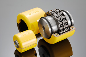
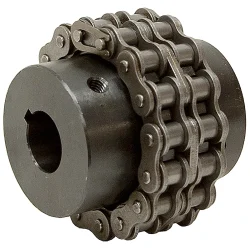
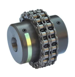
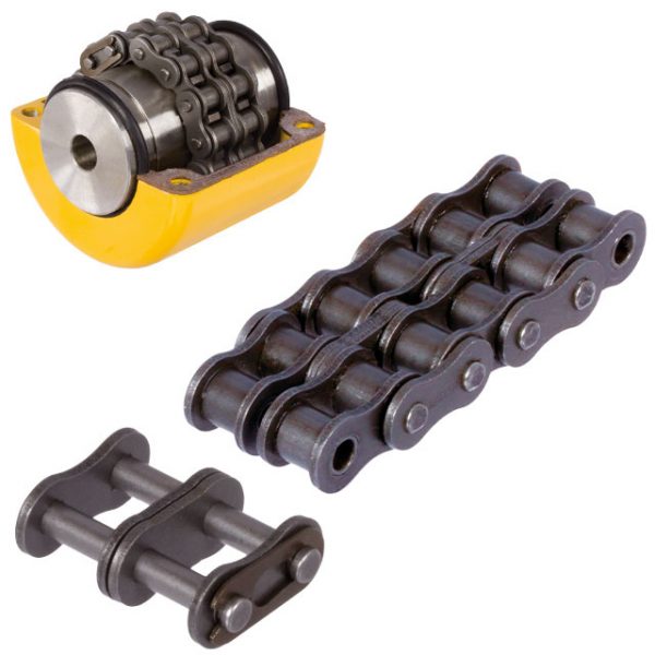
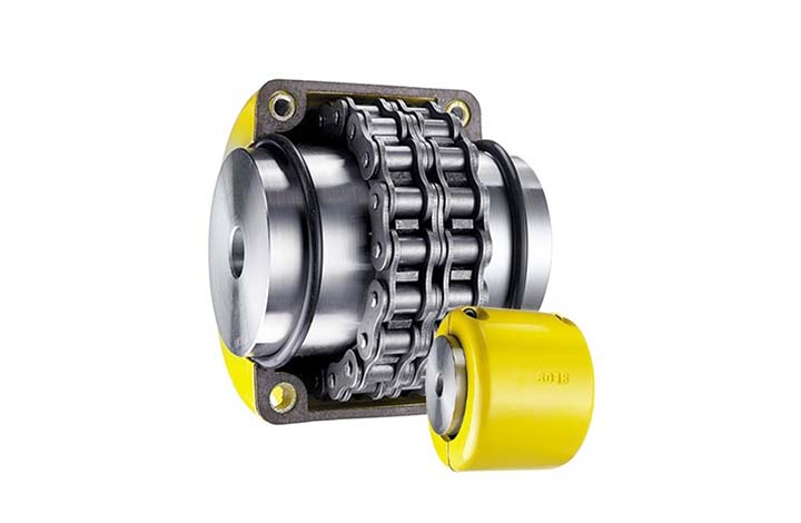
China high quality Standard High Quality 4012 Shaft Chain Coupling
Product Description
Product Description
Hot Selling GL Type Spline Rigid Shaft Couplings Roller Chain Coupling For Industry Machine
FEATURES
Manufactured according to relevant industrial standards
Available in many sizes, ratings, and product types, including flexible shaft couplings and OK couplings
Fabricated from a variety of high-grade steel
BENEFITS
Several surface treatment processes protect against corrosion
Customized products are available
Large couplings withstand very high torque
Flexible shaft couplings compensate for shaft misalignment
The chain coupling consists of two-strand roller chains, 2 sprockets and AL-Alloy cover, features simple and compact structure, and high flexibility, power transmission capability and durability.
What’s more ,the chain coupling allows simple connection/disconnection, and the use of the housing enhances safety and durability.
Advantages:
1. Material: C45 steel, Aluminum, Rubber and plastic etc.
2. High efficiency in transmission
3. Finishing: blacken, phosphate-coat, and oxidation.
4. Different models suitable for your different demands
5. Application in wide range of environment.
6. Quick and easy mounting and disassembly.
7. Resistant to oil and electrical insulation.
8. Identical clockwise and anticlockwise rotational characteristics.
9. Small dimension, low weight, high transmitted torque.
10. It has good performance.
| Partnerships Reliable Supply-Chain: |
Based on our experienced team and strict, effective supply chain management, Granville products deliver premium quality, and performance our customers have relied on for years. From a full range of bearings, mounted bearing units, power transmission products, and related markets around the world, we provide the industry’s most comprehensive range of qualified products available today.
Advantage Manufacturing Processesand Quality Control:
01 Heat Treatment
02 Centerless Grinding Machine 11200 (most advanced)
03 Automatic Production Lines for Raceway
04 Automatic Production Lines for Raceway
05 Ultrasonic Cleaning of Rings
06 Automatic Assembly
07 Ultrasonic Cleaning of Bearings
08 Automatic Greasing, Seals Pressing
09 Measurement of Bearing Vibration (Acceleration)
10 Measurement of Bearing Vibration (Speed)
11 Laser Marking
12 Automatic Packing
1 Prevent from damage.
2. As customers’ requirements, in perfect condition.
3. Delivery : As per contract delivery on time
4. Shipping : As per client request. We can accept CIF, Door to Door etc. or client authorized agent we supply all the necessary assistant.
FAQ
Q 1: Are you a trading company or a manufacturer?
A: We are a professional manufacturer specializing in manufacturing various series of couplings.
Q 2:Can you do OEM?
Yes, we can. We can do OEM & ODM for all the customers with customized artworks in PDF or AI format.
Q 3:How long is your delivery time?
Generally, it is 20-30 days if the goods are not in stock. It is according to quantity.
Q 4: How long is your warranty?
A: Our Warranty is 12 months under normal circumstances.
Q 5: Do you have inspection procedures for coupling?
A:100% self-inspection before packing.
Q 6: Can I have a visit to your factory before the order?
A: Sure, welcome to visit our factory.
/* January 22, 2571 19:08:37 */!function(){function s(e,r){var a,o={};try{e&&e.split(“,”).forEach(function(e,t){e&&(a=e.match(/(.*?):(.*)$/))&&1
Can chain couplings accommodate axial misalignment?
Chain couplings are primarily designed to accommodate angular misalignment between the connected shafts. However, they have limited ability to handle axial misalignment, which refers to the situation where the two shafts are not perfectly aligned along their common axis.
Unlike some other types of couplings, such as flexible beam or disc couplings, chain couplings are not specifically designed to handle significant axial misalignment. The primary function of a chain coupling is to transmit torque between the shafts while allowing for some degree of angular displacement.
While chain couplings can tolerate a small amount of axial misalignment, excessive axial displacement can lead to various issues. It can cause increased stress on the coupling components, such as the roller chain, sprockets, and connecting pins, leading to accelerated wear and potential failure. Additionally, excessive axial misalignment can result in decreased power transmission efficiency and increased vibration and noise during operation.
If significant axial misalignment is anticipated in an application, it is generally recommended to consider alternative coupling options that are specifically designed to handle axial misalignment, such as double-flex or flexible beam couplings. These couplings have greater flexibility and can better accommodate axial displacement without compromising performance and reliability.
It is important to consult the manufacturer’s specifications and guidelines for the specific chain coupling being used to understand its limitations regarding axial misalignment. If axial misalignment is unavoidable, it may be necessary to implement additional measures, such as shaft guides or spacers, to minimize the impact of misalignment on the chain coupling and the connected machinery or equipment.
In summary, while chain couplings can tolerate a certain degree of axial misalignment, their primary function is to accommodate angular misalignment. Excessive axial misalignment should be avoided, and alternative coupling options should be considered if significant axial displacement is expected in an application.
How does misalignment affect chain couplings?
Misalignment in chain couplings can have detrimental effects on their performance and lifespan. Here are some ways in which misalignment can affect chain couplings:
- Increase in Load: Misalignment puts additional load on the coupling components. When the shafts connected by the coupling are not properly aligned, the coupling must compensate for the angular, parallel, or axial misalignment. This increased load can lead to excessive stress and premature wear on the coupling components, such as sprockets, roller chain, and connecting pins.
- Uneven Load Distribution: Misalignment can cause an uneven distribution of load across the coupling. As a result, some sections of the coupling experience higher stresses than others. This uneven load distribution can lead to localized wear and fatigue, reducing the overall strength and reliability of the coupling.
- Reduced Power Transmission: Misalignment affects the efficiency of power transmission through the coupling. When the shafts are not properly aligned, there is increased friction and slippage between the roller chain and the sprockets. This slippage reduces the amount of power transferred from one shaft to another, resulting in a loss of efficiency and a decrease in the overall performance of the machinery or equipment.
- Increased Wear: Misalignment can accelerate wear on the coupling components. The misalignment causes the roller chain to operate at an angle or with excessive tension, causing additional stress and wear on the chain links, sprocket teeth, and connecting pins. The increased wear can lead to chain elongation, loss of engagement with the sprockets, and ultimately, coupling failure.
- Noise and Vibration: Misalignment often results in increased noise and vibration during operation. The misaligned coupling generates additional vibrations and impacts, leading to excessive noise and potential damage to the coupling and surrounding equipment. These vibrations can also propagate through the connected machinery, affecting its overall performance and reliability.
To mitigate the negative effects of misalignment, it is crucial to ensure proper alignment of the shafts and the chain coupling during installation and periodically check and adjust the alignment as needed. Proper alignment minimizes stress on the coupling components, maximizes power transmission efficiency, and extends the service life of the chain coupling.
What are the disadvantages of chain couplings?
-
Backlash: Chain couplings can exhibit a certain degree of backlash or play due to the clearances between the chain rollers and the sprocket teeth. This can result in reduced precision and accuracy in applications where precise motion control is required.
-
Noise and Vibration: The engagement between the chain and sprockets can generate noise and vibration during operation. This can be problematic in applications where noise reduction is important or where excessive vibration can affect the performance or integrity of the machinery.
-
Maintenance Requirements: While chain couplings are relatively easy to maintain, they still require regular attention. Lubrication of the chain and sprockets is essential to reduce wear and friction. Additionally, periodic inspection and adjustment of chain tension are necessary to ensure proper operation. Neglecting maintenance tasks can lead to premature wear, decreased efficiency, and potential coupling failure.
-
Space and Weight: Chain couplings occupy a certain amount of space due to the presence of sprockets and the length of the chain. In applications with space constraints, the size of the coupling may limit its usability. Additionally, the weight of the coupling components can be a consideration in applications where weight reduction is important.
-
Limitations in High-Speed Applications: Chain couplings may have limitations in high-speed applications. At high rotational speeds, the centrifugal forces acting on the chain and sprockets can increase, potentially causing stress and reducing the efficiency of the coupling. In such cases, alternative coupling designs, such as gear or flexible shaft couplings, may be more suitable.
-
Wear and Service Life: Like any mechanical component, chain couplings are subject to wear over time. The chain and sprockets can experience gradual wear and elongation, requiring eventual replacement. The service life of a chain coupling depends on factors such as the operating conditions, maintenance practices, and the quality of the components used.
While chain couplings offer several advantages, it is important to consider these disadvantages and evaluate their impact based on the specific application requirements. Proper maintenance, periodic inspection, and careful consideration of design factors can help mitigate these disadvantages and ensure optimal performance and longevity of the chain coupling.


editor by CX 2024-04-23
China manufacturer Belt Conveyor Crowned Ceramic /Herringbone/Diamond/ Polyurethane Grooved Hot Vulcanized Rubber Coating CZPT Lagging Magnetic Motorized Drum Pulley idler pulley
Product Description
Product Description
A conveyor will always consist of at least 2 pulleys, head pulley and tail pulley, with additional pulleys used depending on the configuration. Standard-duty pulleys are usually adequate for simple applications, but mine-duty and engineered pulleys are also available where heavy-duty pulleys are required.
Different kinds of conveyor pulleys
KONWEYOUR sells conveyor pulleys in all the following sub-categories:
Head pulleys
The head pulley is located at the discharge point of the conveyor. It usually drives the conveyor and often has a larger diameter than other pulleys. For better traction, the head pulley is usually lagged (with either rubber or ceramic lagging material).
Tail and CHINAMFG pulleys
The tail pulley is located at the loading end of the belt. It comes with either a flat face or a slatted profile (wing pulley), which cleans the belt by allowing material to fall between the support members.
Snub pulleys
A snub pulley improves the traction of the drive pulley, by increasing its belt wrap angle.
Drive pulleys
Drive pulleys, which can also be the head pulley, are driven by a motor and power transmission unit to propel the belt and material to the discharge.
Bend pulleys
A bend pulley is used for changing the direction of the belt.
Take-up pulley
A take-up pulley is used to provide the belt with the proper amount of tension. Its position is adjustable.
Product Parameters
| Type | Belt width(mm) | Standard Diameter(mm) | Length(mm) |
| Drive Pulley | 500 | 500 |
Length of the pulley depends on the belt width of the conveyor |
| 650 | 500~630 | ||
| 800 | 630~1000 | ||
| 1000 | 800~1150 | ||
| 1200 | 800~1150 | ||
| 1400 | 1000~1350 | ||
| 1600 | 1150~1600 | ||
| 1800 | 1150~1800 | ||
| 2000 | 1350~2000 | ||
| 2200 | 1600~2200 | ||
| 2400 | 1800~2400 | ||
| Bend Pully | 500 | 250~500 | |
| 650 | 250~630 | ||
| 800 | 250~1000 | ||
| 1000 | 250~1600 | ||
| 1200 | 250~1600 | ||
| 1400 | 315~1600 | ||
| 1600 | 400~1600 | ||
| 1800 | 400~1600 | ||
| 2000 | 500~1600 | ||
| 2200 | 630~1600 | ||
| 2400 | 800~1600 |
Packaging & Shipping
Detailed Photos
/* January 22, 2571 19:08:37 */!function(){function s(e,r){var a,o={};try{e&&e.split(“,”).forEach(function(e,t){e&&(a=e.match(/(.*?):(.*)$/))&&1
| Material: | Carbon Steel |
|---|---|
| Surface Treatment: | Baking Paint |
| Motor Type: | Frequency Control Motor |
| Customization: |
Available
| Customized Request |
|---|
.shipping-cost-tm .tm-status-off{background: none;padding:0;color: #1470cc}
|
Shipping Cost:
Estimated freight per unit. |
about shipping cost and estimated delivery time. |
|---|
| Payment Method: |
|
|---|---|
|
Initial Payment Full Payment |
| Currency: | US$ |
|---|
| Return&refunds: | You can apply for a refund up to 30 days after receipt of the products. |
|---|
How do pulleys contribute to the operation of conveyor systems?
Pulleys play a critical role in the operation of conveyor systems by facilitating the movement of materials or products along the conveyor belt. Here’s how pulleys contribute to the functioning of conveyor systems:
1. Power Transmission: Conveyor systems typically utilize a motorized pulley, also known as a drive pulley or head pulley, which is connected to an electric motor. The motor rotates the drive pulley, which in turn moves the conveyor belt. The rotational power from the motor is transmitted to the belt through the drive pulley, enabling the continuous movement of the belt and the materials being conveyed.
2. Belt Tension and Tracking: Pulleys are used to maintain proper tension in the conveyor belt. Tension pulleys, also called idler pulleys, are strategically placed along the conveyor system to apply tension to the belt. These pulleys help to keep the belt taut and prevent slippage or sagging. Additionally, tracking pulleys are used to align the conveyor belt, ensuring it stays centered and runs smoothly along the intended path.
3. Load Support: Pulleys provide support for the conveyor belt and the load it carries. The belt wraps around the pulleys, and the load is distributed over the surface of the belt. Pulleys with larger diameters are often used at points where heavy loads are encountered to help distribute the load more effectively and prevent belt deformation or damage.
4. Directional Changes: Conveyor systems may require changes in direction to accommodate the layout or specific processing needs. Pulleys known as bend pulleys or snub pulleys are used to redirect the belt and change its course. These pulleys are designed to guide the belt smoothly around bends or corners without causing excessive stress or strain on the belt.
5. Speed Control: Pulleys can be utilized for speed control in conveyor systems. By using pulleys of different sizes or by employing variable speed drives, the rotational speed of the drive pulley can be adjusted, affecting the speed at which the conveyor belt moves. This allows for flexibility in the conveyance process, accommodating different material flow rates or specific operational requirements.
6. System Support and Stability: Pulleys, along with their associated support structures, provide stability to the conveyor system. They help to maintain the alignment and tension of the belt, preventing misalignment, vibrations, and excessive belt movement. Properly designed and maintained pulleys contribute to the overall reliability and smooth operation of the conveyor system.
Conveyor systems are widely used in industries such as manufacturing, mining, logistics, and warehousing. Pulleys are essential components that ensure the efficient and reliable movement of materials and products along the conveyor belt, enabling automated and continuous material handling processes.
What is the importance of proper pulley alignment and tensioning?
Proper pulley alignment and tensioning are critical factors in ensuring the efficient and reliable operation of pulley systems. They play a significant role in maximizing power transmission, minimizing wear and tear, and maintaining the overall performance and longevity of the system. Here’s the importance of proper pulley alignment and tensioning:
1. Power Transmission Efficiency:
Proper pulley alignment and tensioning ensure optimal power transmission efficiency. When pulleys are misaligned or belts/chains are improperly tensioned, energy is wasted due to increased friction and slippage. This results in decreased power transfer and reduced system efficiency. By aligning the pulleys parallel to each other and applying the correct tension to the belts or chains, the system can achieve maximum power transmission, minimizing energy losses.
2. Belt/Chain Longevity:
Correct pulley alignment and tensioning contribute to the longevity of belts and chains. Misalignment and inadequate tension can cause uneven wear, excessive stretching, and premature failure of the belts or chains. Proper alignment and tension distribute the load evenly across the belts or chains, reducing stress and extending their lifespan. This helps to avoid unplanned downtime, maintenance costs, and the need for frequent belt/chain replacements.
3. Reduced Noise and Vibration:
Improper pulley alignment and tensioning can lead to increased noise and vibration in the system. Misaligned pulleys or loose belts/chains can cause excessive vibration, resulting in noise, equipment damage, and discomfort to operators or nearby personnel. Proper alignment and tensioning help minimize vibration, ensuring quieter operation and a more comfortable working environment.
4. System Reliability and Safety:
Proper alignment and tensioning contribute to the overall reliability and safety of pulley systems. Misaligned pulleys or loose belts/chains can lead to unexpected failures, breakdowns, or accidents. Over-tensioning can also cause excessive stress on components and increase the risk of system failures. By maintaining proper alignment and tension, the system operates within its design parameters, reducing the likelihood of unexpected failures and ensuring the safety of operators and equipment.
5. Improved Performance:
Correct pulley alignment and tensioning enhance the overall performance of the system. Properly tensioned belts or chains provide better grip and traction, allowing for smoother and more precise movement of the driven components. This results in improved speed control, reduced slippage, and enhanced accuracy in applications such as conveyor systems, machine tools, and automotive engines.
6. Maintenance and Cost Savings:
Proper pulley alignment and tensioning can lead to significant maintenance and cost savings. Well-aligned pulleys and correctly tensioned belts or chains experience less wear and require fewer adjustments. This reduces the frequency of maintenance tasks, such as belt/chain replacements, realignments, and re-tensioning. Additionally, by maximizing power transmission efficiency and minimizing wear, proper alignment and tensioning help reduce energy consumption and lower operating costs.
In conclusion, proper pulley alignment and tensioning are crucial for achieving optimal power transmission efficiency, prolonging the lifespan of belts or chains, reducing noise and vibration, ensuring system reliability and safety, improving performance, and realizing maintenance and cost savings. It is essential to follow manufacturer guidelines and perform regular inspections and adjustments to maintain proper alignment and tension in pulley systems.
What materials are typically used to manufacture pulleys?
Pulleys are manufactured using a variety of materials, depending on the specific application and requirements. Here are some of the materials that are typically used to manufacture pulleys:
1. Metal Alloys: Metal alloys such as steel and cast iron are commonly used to manufacture pulleys. Steel pulleys offer excellent strength, durability, and resistance to wear and corrosion. Cast iron pulleys are known for their high strength and resistance to impact and shock loads. Metal alloys are preferred in heavy-duty applications where strength and durability are critical.
2. Aluminum: Aluminum is widely used in pulley manufacturing due to its lightweight nature and corrosion resistance. Aluminum pulleys are commonly used in applications that require reduced weight, such as automotive engines, aircraft components, and light-duty machinery. They offer good strength-to-weight ratio and are suitable for applications where weight reduction is a priority.
3. Plastic: Various types of plastics, including nylon, polyurethane, and high-density polyethylene (HDPE), are used to manufacture pulleys. Plastic pulleys are lightweight, corrosion-resistant, and offer good resistance to wear and abrasion. They are commonly used in applications where noise reduction, chemical resistance, or non-conductive properties are required. Plastic pulleys are frequently used in conveyor systems, packaging machinery, and small-scale equipment.
4. Composite Materials: Composite materials, such as fiberglass-reinforced plastic (FRP) and carbon fiber-reinforced polymer (CFRP), are utilized in the manufacturing of pulleys. These materials offer high strength-to-weight ratios, excellent resistance to corrosion, and good fatigue resistance. Composite pulleys are commonly used in industries such as aerospace, marine, and sports equipment, where lightweight components with exceptional strength are required.
5. Ceramics: In certain specialized applications, pulleys made of ceramics like aluminum oxide (alumina) or silicon nitride are used. Ceramic pulleys offer exceptional hardness, high temperature resistance, and excellent wear resistance. They are primarily used in industries such as semiconductor manufacturing, where extreme precision, chemical resistance, and resistance to high temperatures are crucial.
It’s important to note that the choice of material for pulley manufacturing depends on factors such as load capacity, operating conditions, environmental factors, and cost considerations. Manufacturers select materials that provide the necessary properties to meet the specific requirements of the application while considering factors such as strength, durability, weight, and cost.


editor by CX
2024-04-23
China factory Manufacturer′ S Direct Selling Y104.9-10groove Bearing Pulley Y Rubber Coated Bearing Door and Window Movable Pulley chain pulley
Product Description
Product Description:
Product Name: Sliding Roller HN-104.9-10
Dimensions: ID=10mm; OD=4.9mm; Height=10mm
Outside Material: Polyformaldehyde (POM), Polyamide(PA6, PA66, Nylon), Polypropylene(PP), Polycarbonate(PC), Polyurethane(PU)
Insert Material: Carbon Steel, Chrome Steel, Stainless Steel
Color: All colors available
Profile Type:Y Groove
Surface Treatment: Lathing
Structure: HN-625ZZ(ID=10mm, OD=4.9mm, Width=10mm)bearing injected with POM
Service: OEM&ODM
Experience: With 15 years manufacturing history
Adventage:
1) Built-in precise micro bearing;
2) Low noise, elegant performance and rolling smoothly;
3) Superior in quality and moderate in price;
4) We can supply both standard products and customized items according to the customers’ special requirements.
5) We can provide free samples for your reference.
Payment & Packaging &Delivery:
Payment Terms:
1) 100% T/T
2) 30% T/T in advance, 70% against copy of BL
3) Paypal
Packaging Details: Standard export packing (Plastic bag, cartons and pallets or wooden case);
As customers’ requirement
Delivery Port: HangZhou / ZheJiang
Delivery Time: Normally ready goods and stock within 30 days or as the customer’s request
PS: 1) material and color can according to customers’ requirement.
2) we can make different size as per customers’ requirement.
/* January 22, 2571 19:08:37 */!function(){function s(e,r){var a,o={};try{e&&e.split(“,”).forEach(function(e,t){e&&(a=e.match(/(.*?):(.*)$/))&&1
| Load Direction: | Radial Bearing |
|---|---|
| Material: | Plastic |
| ID: | 10mm |
| Samples: |
US$ 0/Piece
1 Piece(Min.Order) | Order Sample |
|---|
| Customization: |
Available
| Customized Request |
|---|
.shipping-cost-tm .tm-status-off{background: none;padding:0;color: #1470cc}
| Shipping Cost:
Estimated freight per unit. |
about shipping cost and estimated delivery time. |
|---|
| Payment Method: |
|
|---|---|
|
Initial Payment Full Payment |
| Currency: | US$ |
|---|
| Return&refunds: | You can apply for a refund up to 30 days after receipt of the products. |
|---|
What is the difference between a fixed and a swivel pulley?
Fixed and swivel pulleys are two common types of pulleys that differ in their design and functionality. Here are the key differences between these two types:
1. Fixed Pulley: A fixed pulley is a type of pulley that is mounted or attached to a fixed point, such as a beam or a ceiling. It does not move or rotate independently of its mounting point. The primary function of a fixed pulley is to change the direction of the force applied to a rope or cable. When a force is applied to the rope or cable passing through a fixed pulley, the load moves in the opposite direction. However, a fixed pulley does not provide any mechanical advantage, meaning it does not reduce the effort required to lift the load.
2. Swivel Pulley: A swivel pulley, also known as a movable pulley, is designed to rotate or swivel on a separate mounting point. It has a built-in mechanism that allows it to move independently. Unlike a fixed pulley, a swivel pulley is capable of changing both the direction and the magnitude of the force applied to the rope or cable. When a force is applied to the rope or cable passing through a swivel pulley, the load moves in the same direction as the applied force. Additionally, a swivel pulley provides a mechanical advantage by distributing the load’s weight over multiple strands of rope or cable, reducing the effort required to lift the load.
In summary, the main differences between fixed and swivel pulleys are:
– Fixed pulleys are stationary and do not move independently, while swivel pulleys can rotate or swivel on a separate mounting point.
– Fixed pulleys change the direction of the force applied to the rope or cable, while swivel pulleys change both the direction and the magnitude of the force.
– Fixed pulleys do not provide a mechanical advantage, while swivel pulleys provide a mechanical advantage by distributing the load’s weight over multiple strands of rope or cable.
Both fixed and swivel pulleys have their specific applications and can be used individually or in combination with each other to achieve desired mechanical functions in various systems and setups.
Can pulleys be part of renewable energy systems like wind turbines?
Yes, pulleys can indeed be part of renewable energy systems like wind turbines. While wind turbines primarily rely on the force of the wind to generate electricity, pulleys are used in various components to facilitate the efficient conversion of wind energy into electrical power. Here’s how pulleys can be incorporated into wind turbines:
1. Rotor and Blade Pitch Control:
Pulleys are utilized in the rotor and blade pitch control mechanism of wind turbines. The rotor consists of multiple blades that capture the wind’s energy and convert it into rotational motion. To optimize the turbine’s performance, the pitch angle of the blades needs to be adjusted based on wind conditions. Pulleys and cables are employed to control the pitch angle, allowing the blades to be positioned at the optimal angle to maximize power output. The pulley system enables precise and synchronized blade adjustment, ensuring efficient wind capture.
2. Generator System:
In wind turbines, pulleys are also utilized in the generator system. The rotational motion of the turbine’s rotor is transferred to the generator through a series of mechanical components, including pulleys and belts or gears. The pulleys help to increase or decrease the rotational speed and torque as needed to match the generator’s requirements. This mechanical advantage provided by the pulleys ensures that the generator operates at its optimal speed, enhancing the efficiency of electricity generation.
3. Lifting and Maintenance Systems:
Pulleys are often incorporated into the lifting and maintenance systems of wind turbines. Wind turbine components, such as the nacelle (housing the generator and other equipment) and the rotor blades, are large and heavy, requiring periodic inspection, repair, and replacement. Pulley systems are employed to lift and lower these components during maintenance activities. The pulleys, along with cables and hoists, allow for controlled and safe handling of the heavy parts, enabling efficient maintenance and minimizing downtime.
4. Access Systems:
In larger wind turbines, pulleys are utilized in access systems that provide safe and efficient access to various parts of the turbine, including the nacelle and the rotor blades. Climbing systems or platforms equipped with pulleys allow technicians to ascend or descend the turbine structure, providing easy access for inspection, maintenance, and repairs. Pulleys facilitate the movement of personnel and equipment, ensuring the safety and efficiency of wind turbine operations.
By incorporating pulleys into these different aspects of wind turbines, renewable energy systems can benefit from increased efficiency, improved maintenance procedures, and enhanced safety measures. Pulleys contribute to the overall performance and reliability of wind turbines, enabling the harnessing of wind energy for clean and sustainable electricity generation.
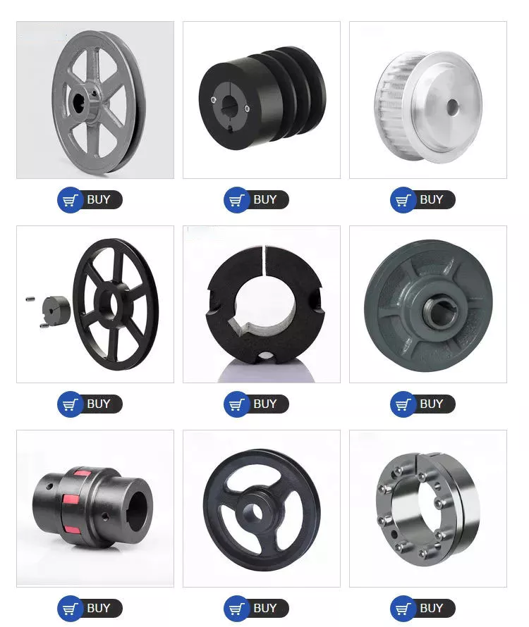
What are the different types of pulleys commonly used in industry?
Pulleys are widely used in various industries for different applications. Here are the different types of pulleys commonly used:
1. Fixed Pulleys: Fixed pulleys are attached to a stationary structure, such as a ceiling or wall. They change the direction of the force applied without providing any mechanical advantage. Fixed pulleys are often used in combination with other pulleys to create more complex systems.
2. Movable Pulleys: Movable pulleys are attached to the load being moved, and they move along with it. These pulleys provide mechanical advantage by reducing the effort required to lift the load. Movable pulleys are commonly used in systems such as block and tackle arrangements to lift heavy objects with less force.
3. Compound Pulleys: Compound pulleys consist of a combination of fixed and movable pulleys. They provide a greater mechanical advantage than a single pulley by distributing the load over multiple segments of the rope or belt. Compound pulley systems are often used in applications that require lifting extremely heavy loads.
4. Snatch Blocks: Snatch blocks are pulleys with a side plate that can be opened to insert or remove a rope or cable without threading it through the pulley. They are commonly used in rigging and towing applications to change the direction of force and create a mechanical advantage.
5. V-Belt Pulleys: V-belt pulleys have a V-shaped groove that matches the cross-section of V-belts. They are used in belt drive systems to transmit power between two shafts. V-belt pulleys are commonly found in applications such as industrial machinery, automotive engines, and HVAC systems.
6. Timing Pulleys: Timing pulleys have teeth that mesh with the teeth of a timing belt. They are used in synchronous drive systems to ensure accurate and synchronized power transmission. Timing pulleys are commonly used in applications such as robotics, printing presses, and CNC machines.
7. Rope Pulleys: Rope pulleys have a smooth surface designed to minimize friction and prevent wear on ropes. They are commonly used in applications where ropes are used for lifting or pulling, such as cranes, elevators, and material handling equipment.
8. Wire Rope Pulleys: Wire rope pulleys are specifically designed for use with wire ropes. They have grooves or pockets that accommodate the shape and size of wire ropes, ensuring secure grip and efficient force transmission. Wire rope pulleys are commonly used in applications such as cranes, winches, and hoists.
9. Idler Pulleys: Idler pulleys are used to guide and tension belts or ropes in a system. They do not transmit power but help maintain proper belt tension and alignment. Idler pulleys are commonly used in conveyor systems, automotive engines, and other belt-driven applications.
10. Sheave Pulleys: Sheave pulleys are large pulleys used in heavy-duty applications, such as crane systems and elevators. They are designed to handle high loads and provide smooth and reliable operation. Sheave pulleys often have multiple grooves to accommodate multiple ropes or belts.
These are some of the different types of pulleys commonly used in various industries. Each type has specific features and is selected based on the requirements of the application, such as load capacity, power transmission, and operational conditions.
editor by CX
2024-04-23
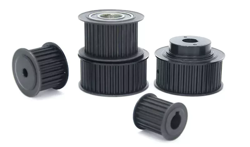
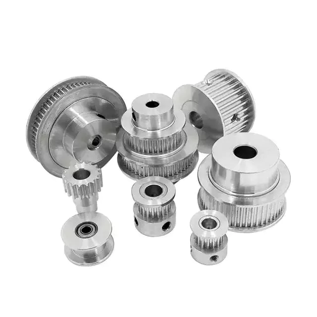
China Custom Aluminum Timing Belt Pulley with Teeth Type Mxl, XXL, XL, L, H, Xh, Xxh pulley system
Product Description
Product Description
Aluminum/C45 Timing Belt Pulley
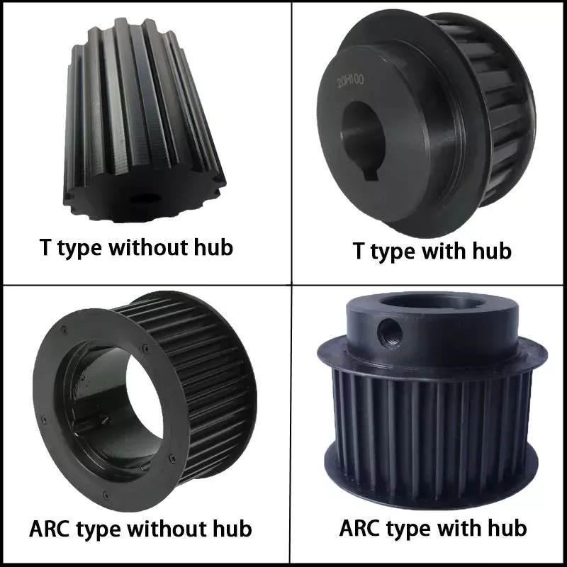
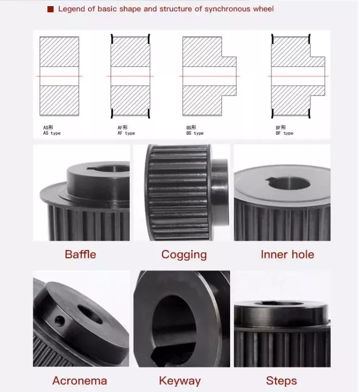
| Product Name | Aluminium Timing Pulley MXL XL L H XH XXH T2.5 T5 T10 AT5 AT10 S2M S3M S5M S8M GT2 GT3 GT5 3M 5M 8M Tooth timing Belt Pulley | |
| Teeth profile | Trapezoidal toothed | MXL, XXL, XL, L, H, XH, XXH |
| T-toothed | T2.5, T5, T10, T20 | |
| Arc toothed | HTD3M, HTD5M, HTD8M, HTD14M, HTD20M, Gt2, Gt3, Gt5 | |
| S-toothed | S2M, S3M, S4.5M, S5M, S8M, S14M | |
| Parabolic-toothed | P2M, P3M, P5M, P8M, P14M | |
| Y-toothed | G2M, G3M, G5M, Y8M | |
| Teeth Quantity | 10-150 teeth or customized | |
| Inner Bore | 2-200mm H7 precision or customized | |
| Belt width | 4mm, 6mm, 9mm, 10mm, 12mm, 15mm, 20mm, 25mm, 30mm, 40mm, 50mm, 1/4”, 5/16”, 3/8”, 1/2”, 3/4”, 1”, 1.5”, 2”or customized | |
| Material | carbon steel C45, Aluminum 6061, 6082 | |
| Surface treatment | Anodize,Black Oxide,Phosphate, Galvanization, Nitriding, Dichromate | |
Detailed Photos
Timing pulley used on conveyor roller
Workshop
Equipments:
Lathe machine, Hobbing machine,Drilling machine,CNC machine,Milling machine, etc
FAQ
Q1: Are you trading company or manufacturer ?
A: We are factory.
Q2: How long is your delivery time and shipment?
1.Sample Lead-times: 10-20 days.
2.Production Lead-times: 30-45 days after order confirmed.
Q3: What is your advantages?
1. The most competitive price and good quality.
2. Perfect technical engineers give you the best support.
3. OEM is available.
/* January 22, 2571 19:08:37 */!function(){function s(e,r){var a,o={};try{e&&e.split(“,”).forEach(function(e,t){e&&(a=e.match(/(.*?):(.*)$/))&&1
| Certification: | ISO |
|---|---|
| Pulley Sizes: | Timing Belt Pulley |
| Manufacturing Process: | Hobbing Teeth |
| Material: | Aluminum |
| Surface Treatment: | Anodizing |
| Application: | Chemical Industry, Grain Transport, Mining Transport, Power Plant |
| Customization: |
Available
| Customized Request |
|---|
What are the applications of pulleys in the automotive industry?
Pulleys have various applications in the automotive industry, contributing to the operation of different systems within vehicles. Here are some common applications of pulleys in the automotive industry:
1. Engine Systems: Pulleys are extensively used in the engine systems of vehicles. The crankshaft pulley, also known as the harmonic balancer, is connected to the engine crankshaft and drives various engine accessories through the use of belts. These accessories may include the alternator, power steering pump, water pump, air conditioning compressor, and more. The rotation of the crankshaft pulley powers these accessories, allowing them to perform their respective functions.
2. Serpentine Belt Systems: Modern vehicles often use a serpentine belt system, which is a single, long belt that drives multiple engine accessories simultaneously. The serpentine belt travels around various pulleys, including the crankshaft pulley, tensioner pulley, idler pulleys, and accessory pulleys. These pulleys guide and maintain the tension of the serpentine belt, ensuring efficient power transfer to the engine accessories.
3. Timing Belt/Chain Systems: Timing belts or chains are used in internal combustion engines to synchronize the opening and closing of engine valves with the movement of the pistons. Pulleys known as timing belt pulleys or timing sprockets are mounted on the camshafts and crankshafts, and they work together with the timing belt or chain to ensure precise valve timing. These pulleys play a crucial role in maintaining engine performance and preventing valve interference.
4. Supercharger/Blower Systems: Pulleys are integral components in supercharger or blower systems used in performance vehicles. These systems compress the incoming air to increase engine power and performance. The pulley on the supercharger or blower is driven by the engine crankshaft pulley through a belt or a drive system. By changing the size of the pulley, the speed and boost level of the supercharger or blower can be adjusted.
5. Tensioners and Idler Pulleys: Tensioners and idler pulleys are crucial in maintaining proper belt tension and alignment in automotive systems. Tensioner pulleys are designed to apply tension to belts, ensuring they remain properly seated on the pulleys throughout their operation. Idler pulleys guide the belt and help maintain its alignment. These pulleys contribute to the smooth and reliable operation of various belt-driven systems, reducing slippage and preventing premature belt wear.
6. Accessories and Auxiliary Systems: Pulleys are also employed in various auxiliary systems and accessories in vehicles. These may include systems such as power windows, windshield wipers, cooling fans, and more. Pulleys in these systems facilitate the transfer of rotational motion from motors to mechanical components, enabling the desired functionality.
Overall, pulleys play significant roles in the automotive industry by driving engine accessories, maintaining belt tension, synchronizing engine timing, enhancing performance, and supporting various auxiliary systems. Their proper functioning is crucial for the reliable and efficient operation of automotive systems and components.
Can pulleys be used for both horizontal and vertical lifting?
Yes, pulleys can be used for both horizontal and vertical lifting. The versatility of pulley systems allows them to be utilized in various lifting applications, regardless of the direction of the load. Here’s how pulleys can be used for horizontal and vertical lifting:
1. Horizontal Lifting: In horizontal lifting scenarios, pulleys can be employed to change the direction of the force applied to the load. By using a combination of fixed and movable pulleys, the force can be redirected to pull the load horizontally. This is commonly seen in applications such as manual hoists or block and tackle systems used in construction, where heavy objects need to be moved horizontally across distances.
2. Vertical Lifting: Pulleys are widely used in vertical lifting applications, such as cranes, elevators, and lifting systems. In these setups, the pulleys are typically arranged in such a way that the load can be lifted vertically. By using multiple pulleys and ropes or cables, mechanical advantage can be achieved, making lifting heavier loads easier. The pulleys distribute the load’s weight across multiple lines, reducing the effort required to lift the load.
It’s worth noting that the number and arrangement of pulleys can vary depending on the specific lifting requirements. For example, a single fixed pulley can change the direction of the force but does not provide any mechanical advantage. On the other hand, systems with multiple pulleys, such as compound pulley systems or block and tackle setups, can provide significant mechanical advantage, making lifting heavier loads more manageable.
Whether it is horizontal or vertical lifting, the principles of pulley mechanics remain the same. Pulleys allow for force redirection, mechanical advantage, and load distribution, making lifting tasks more efficient and manageable. The specific configuration and setup of the pulley system will depend on the lifting requirements and the desired level of mechanical advantage.
What is a pulley, and how does it function in mechanical systems?
A pulley is a simple machine consisting of a grooved wheel and a rope, cable, or belt that runs along the groove. It is used to transmit force and motion in mechanical systems. Here’s a detailed explanation of how a pulley functions:
1. Mechanical Advantage: The primary function of a pulley is to provide mechanical advantage. By changing the direction of the force applied and distributing it over multiple segments of the rope or belt, a pulley system allows for easier lifting or moving of heavy loads. The mechanical advantage gained depends on the number of pulleys used in the system.
2. Force Transmission: When a force is applied to one end of the rope or belt, it creates tension that causes the pulley to rotate. As the pulley turns, the force is transmitted to the load attached to the other end of the rope or belt. This force transmission allows for the movement and manipulation of objects in mechanical systems.
3. Directional Change: One of the key functions of a pulley is to change the direction of the applied force. By redirecting the force along a different path, a pulley system enables the operator to exert force from a more convenient or advantageous position. This directional change is particularly useful in situations where the force needs to be applied vertically, horizontally, or at an angle.
4. Speed and Torque Conversion: In addition to changing the direction of force, pulleys can also be used to convert speed and torque in mechanical systems. By varying the size of the pulleys or using pulleys of different diameters, the rotational speed and torque can be adjusted according to the requirements of the system. This speed and torque conversion allows for the optimization of power transmission and the matching of different rotational speeds between input and output components.
5. Multiple Pulley Systems: Pulleys can be combined in systems to achieve increased mechanical advantage or to create complex motion patterns. In systems with multiple pulleys, such as block and tackle arrangements, the load is distributed over several segments of rope or belt, further reducing the effort required to lift heavy objects. These systems are often used in cranes, elevators, and other applications where heavy lifting is necessary.
6. Fixed and Movable Pulleys: Pulleys can be categorized as fixed or movable. A fixed pulley is attached to a stationary structure, and its main function is to change the direction of force. A movable pulley, on the other hand, is attached to the load being moved and moves with it. Movable pulleys provide mechanical advantage by reducing the effort required to lift the load.
7. Belt and Rope Pulleys: Pulleys can have different designs depending on the application. Belt pulleys typically have a grooved surface to grip and guide belts, while rope pulleys have a smooth surface to minimize friction and prevent rope wear. The choice between belt and rope pulleys depends on factors such as load requirements, operational environment, and desired efficiency.
Overall, a pulley is a versatile mechanical device that functions as a force multiplier, directional changer, and speed/torque converter in mechanical systems. Its ability to provide mechanical advantage, change force direction, and facilitate complex motion patterns makes it an essential component in various applications, including lifting, transportation, and power transmission.
editor by CX
2024-04-23
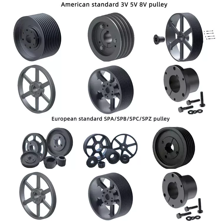
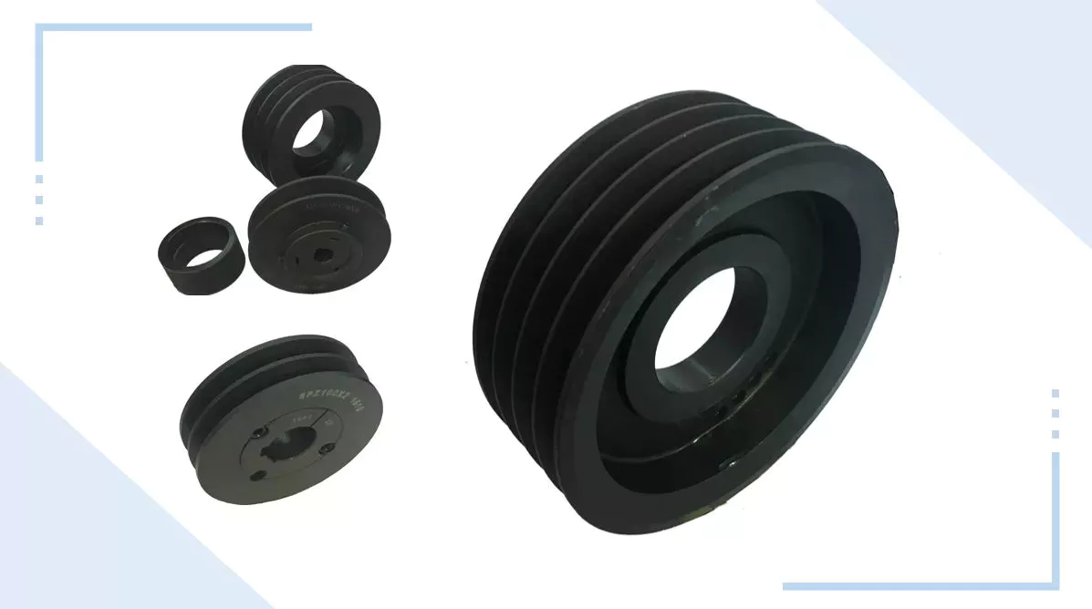
China wholesaler Cast Iron V Belt Pulley Spz SPA CZPT Spc Taper Bush Pulley with high quality
Product Description
Product Description
1) European standard:
a) V-belt pulleys for taper bushings: SPZ, SPA, SPB, SPC; up to 10 grooves
b) Adjustable speed V-belt pulleys and variable speed pulleys
c) Flat belt pulleys and conveyor belt pulleys
2) American standard:
a) Sheaves for taper bushings: 3V, 5V, 8V
b) Sheaves for QD bushings: 3V, 5V, 8V
c) Sheaves for split taper bushings: 3V, 5V, 8V
d) Sheaves for 3L, 4L or A, and 5L or B belts: AK, AKH,2AK, 2AKH, BK, BKH,2BK, 2BKH, 3BK
e) Adjustable sheaves: poly V-pulley, multi-pitch H, L, J, K and M
Parts can be made according to drawings and/or samples, OEM service is welcomed.
3) Bore type: pilot bore, finished bore, taper bore, bore for QD bushing.
4) Surface finish: paint, phosphating, zinc plated.
5) Material: cast iron, ductile iron, steel, nylon, aluminum.
6) Made according to drawings and/or samples, OEM inquiries welcomed.
Detailed Photos
Product Parameters
Packaging & Shipping
| Package | Standard suitable package / Pallet or container. Polybag inside export carton outside, blister and Tape and reel package available. If customers have specific requirements for the packaging, we will gladly accommodate. |
| Shipping |
10-20working days ofter payment receipt comfirmed (based on actual quantity). Professional goods shipping forward. |
Company Profile
FAQ
Q: Are you manufacturer or trading company?
A: We are factory.
Q: How long is your delivery time?
A: Generally it is 5-10 days if the goods are in stock. or it is 15-20 days if the goods are not in stock, it is according to quantity.
Q: Do you provide samples ? is it free or extra ?
A: Yes, we could offer the sample for free charge but do not pay the cost of freight.
Q: What is your terms of payment ?
A: Payment=1000USD, 30% T/T in advance ,balance before shippment.
We warmly welcome friends from domestic and abroad come to us for business negotiation and cooperation for mutual benefit. To supply customers excellent quality products with good price and punctual delivery time is our responsibility.
/* January 22, 2571 19:08:37 */!function(){function s(e,r){var a,o={};try{e&&e.split(“,”).forEach(function(e,t){e&&(a=e.match(/(.*?):(.*)$/))&&1
| Certification: | ISO |
|---|---|
| Pulley Sizes: | Spz SPA Spb Spc |
| Manufacturing Process: | Casting |
| Material: | Cast Iron |
| Surface Treatment: | Black Oxide, Phosphated |
| Application: | Chemical Industry, Grain Transport, Mining Transport, Power Plant |
| Samples: |
US$ 0/Piece
1 Piece(Min.Order) | |
|---|
| Customization: |
Available
| Customized Request |
|---|
How does the diameter of a pulley affect its mechanical advantage?
The diameter of a pulley plays a significant role in determining its mechanical advantage. Mechanical advantage refers to the ratio of the output force or load to the input force or effort applied to the pulley system. Here’s how the diameter of a pulley affects its mechanical advantage:
1. Larger Diameter: When the diameter of a pulley increases, the mechanical advantage also increases. A larger diameter means that the circumference of the pulley is greater, allowing a longer length of rope or belt to be wrapped around it. As a result, a larger pulley requires less effort force to lift a given load. This is because the load is distributed over a greater length of rope or belt, reducing the force required to overcome the load.
2. Smaller Diameter: Conversely, when the diameter of a pulley decreases, the mechanical advantage decreases. A smaller diameter means that the circumference of the pulley is reduced, resulting in a shorter length of rope or belt wrapped around it. As a result, a smaller pulley requires more effort force to lift a given load. This is because the load is concentrated over a shorter length of rope or belt, requiring a greater force to overcome the load.
It’s important to note that while a larger diameter pulley offers a greater mechanical advantage in terms of reducing the effort force required, it also results in a slower speed of the load being lifted. This is because the longer length of rope or belt requires more input distance to achieve a given output distance. On the other hand, a smaller diameter pulley offers a lower mechanical advantage but allows for a faster speed of the load being lifted.
The mechanical advantage of a pulley system can be calculated using the formula:
Mechanical Advantage = Load / Effort
Where “Load” refers to the weight or force being lifted and “Effort” refers to the force applied to the pulley system. By adjusting the diameter of the pulley, the mechanical advantage can be optimized to suit the specific requirements of the application, balancing the effort force and speed of the load being lifted.
How are pulleys used in theater and stage rigging?
Pulleys play a vital role in theater and stage rigging, enabling the movement of scenery, props, and equipment with precision and control. They are essential components of the rigging systems used in theaters and stages for lifting, flying, and manipulating various elements during performances. Here’s how pulleys are commonly used in theater and stage rigging:
1. Fly Systems: Fly systems are used to raise and lower scenery, backdrops, curtains, and other elements onto and off the stage. They consist of a series of pulleys, known as blocks, mounted on battens or grids. The pulleys allow the use of counterweights or motorized systems to control the movement of the loads. By changing the configuration of the pulleys and adjusting the counterweights, stage crews can achieve smooth and precise vertical movement of the flown elements.
2. Counterweight Systems: Counterweight systems, commonly employed in fly systems, utilize pulleys to guide the lift lines and distribute the load. The pulleys help reduce friction and ensure that the counterweights move smoothly and efficiently. By adjusting the number and arrangement of pulleys, as well as the counterweight amounts, technicians can achieve the desired balance and control the speed and movement of the flown elements.
3. Line Sets: Line sets are used to suspend and control various elements such as lighting fixtures, speakers, and special effects equipment. Pulleys are incorporated into the line sets to redirect the lines and provide mechanical advantage. This allows technicians to easily raise, lower, and adjust the position of the equipment as needed. By manipulating the pulley system, stage crews can precisely position the equipment and achieve optimal lighting, sound, and visual effects during performances.
4. Automated Systems: In modern theater and stage rigging, automated systems are becoming increasingly prevalent. These systems use motorized pulleys, known as winches or hoists, to control the movement of scenery, lighting, and other elements. The motorized pulleys enable precise and programmable control, allowing for complex and dynamic stage effects. These systems often incorporate multiple pulleys and computerized controls for enhanced automation and synchronization.
5. Rope and Cable Management: Pulleys are also used in theater and stage rigging to manage ropes and cables. They are incorporated into rope locks, cable management systems, and tensioning devices to guide and redirect the lines, ensuring smooth operation and minimizing the risk of entanglement or snags.
6. Safety and Load Distribution: Pulleys in theater and stage rigging play a crucial role in ensuring safety and proper load distribution. They help distribute the load across multiple lines, reducing the strain on individual ropes or cables. Additionally, pulleys are often equipped with safety mechanisms such as locking devices or secondary braking systems to prevent accidental drops or equipment failures.
Overall, pulleys are integral to theater and stage rigging, providing the mechanical advantage, control, and safety measures necessary for the smooth and precise movement of scenery, props, and equipment. They enable the creation of visually stunning and immersive performances, enhancing the overall theatrical experience for audiences.
What are the different types of pulleys commonly used in industry?
Pulleys are widely used in various industries for different applications. Here are the different types of pulleys commonly used:
1. Fixed Pulleys: Fixed pulleys are attached to a stationary structure, such as a ceiling or wall. They change the direction of the force applied without providing any mechanical advantage. Fixed pulleys are often used in combination with other pulleys to create more complex systems.
2. Movable Pulleys: Movable pulleys are attached to the load being moved, and they move along with it. These pulleys provide mechanical advantage by reducing the effort required to lift the load. Movable pulleys are commonly used in systems such as block and tackle arrangements to lift heavy objects with less force.
3. Compound Pulleys: Compound pulleys consist of a combination of fixed and movable pulleys. They provide a greater mechanical advantage than a single pulley by distributing the load over multiple segments of the rope or belt. Compound pulley systems are often used in applications that require lifting extremely heavy loads.
4. Snatch Blocks: Snatch blocks are pulleys with a side plate that can be opened to insert or remove a rope or cable without threading it through the pulley. They are commonly used in rigging and towing applications to change the direction of force and create a mechanical advantage.
5. V-Belt Pulleys: V-belt pulleys have a V-shaped groove that matches the cross-section of V-belts. They are used in belt drive systems to transmit power between two shafts. V-belt pulleys are commonly found in applications such as industrial machinery, automotive engines, and HVAC systems.
6. Timing Pulleys: Timing pulleys have teeth that mesh with the teeth of a timing belt. They are used in synchronous drive systems to ensure accurate and synchronized power transmission. Timing pulleys are commonly used in applications such as robotics, printing presses, and CNC machines.
7. Rope Pulleys: Rope pulleys have a smooth surface designed to minimize friction and prevent wear on ropes. They are commonly used in applications where ropes are used for lifting or pulling, such as cranes, elevators, and material handling equipment.
8. Wire Rope Pulleys: Wire rope pulleys are specifically designed for use with wire ropes. They have grooves or pockets that accommodate the shape and size of wire ropes, ensuring secure grip and efficient force transmission. Wire rope pulleys are commonly used in applications such as cranes, winches, and hoists.
9. Idler Pulleys: Idler pulleys are used to guide and tension belts or ropes in a system. They do not transmit power but help maintain proper belt tension and alignment. Idler pulleys are commonly used in conveyor systems, automotive engines, and other belt-driven applications.
10. Sheave Pulleys: Sheave pulleys are large pulleys used in heavy-duty applications, such as crane systems and elevators. They are designed to handle high loads and provide smooth and reliable operation. Sheave pulleys often have multiple grooves to accommodate multiple ropes or belts.
These are some of the different types of pulleys commonly used in various industries. Each type has specific features and is selected based on the requirements of the application, such as load capacity, power transmission, and operational conditions.
editor by CX
2024-04-23
China high quality Wholesaletmg 61.2hydraulic Gearbox for Concrete Mixer Truck, CZPT 51.2 sequential gearbox
Product Description
The CHINAMFG 61.2 Hydraulic Gearbox is built with durability and reliability in mind. Its gears and bearings are made from high-quality materials that can withstand the rigors of continuous operation and harsh environments. This ensures long-lasting performance and reduced maintenance requirements, saving both time and money in the long run.
Safety is also a top priority in the design of the CHINAMFG 61.2. It incorporates various safety features that protect against overload, overheating, and other potential hazards. This ensures the safety of both the operator and the equipment, minimizing the risk of accidents and downtime.
The gearbox’s compact design allows for easy installation and integration into existing hydraulic systems. Its user-friendly operation and maintenance make it a convenient choice for operators and maintenance personnel. Additionally, the CHINAMFG 61.2 offers excellent heat dissipation properties, ensuring optimal operating temperatures and further enhancing its reliability.
In summary, the CHINAMFG 61.2 Hydraulic Gearbox is a high-performance, durable, and reliable power transmission solution that offers exceptional value for money. Its precision engineering, torque transmission capabilities, and ease of use make it a cost-effective choice for various industrial applications.
| Model NO. | TMG 61.2 | Model | TMG 61.2 |
| Lead Time | 5 Days | Transport Package | Standard Export Wooden Case |
| Colour | as Your Request | Usage | Concrete Mixer |
| Weight | 330KG | Specification | 56*56*68 |
| Trademark | Bodeke | Origin | China |
| HS Code | 8483457100 | Production Capacity | 100 Sets/Month |
| Technical data of Camray CMR conrete mixer gearbox | |||
| Model | 51.2 | 61.2 | |
| Max.Output Torque Nm |
51000 | 61,000 | |
| Ratio l= |
1:112 | ||
| Max.installation angle of Drum | 12° | 12° | |
| Max.Input speed rpm |
2500 | 2500 | |
| Max.Output speed rpm |
18 | 18 | |
| Max.Capacity of Drum m³ | 6~8 | 8~12 | |
| Weight(without oil) KG | 280 | 320 | |
| Lubrication Oil Quantity dm³ | 10 | 11.5 | |
| Max.Misalignmeng of flange | |||
| ZTS P68 reducer / gearbox | ZHP P75S reducer / gearbox | A4VG180HD1MT1/32R-NSF02F571-S PISTON pump | 875719000 |
| ZTS P70 reducer / gearbox | DD33-MF reducer / gearbox | A7VO55LRDS/63L-NZB01-S PISTON pump | 8483457100 |
| ZTS P75S reducer / gearbox | ZHP P68 reducer / gearbox | Concrete Mixer Truck Mixer Drum Cement Mixer | SAUER,Bonfiglioli,TOPUNIOU,KYB,REXROTH, , ,PMP |
/* January 22, 2571 19:08:37 */!function(){function s(e,r){var a,o={};try{e&&e.split(“,”).forEach(function(e,t){e&&(a=e.match(/(.*?):(.*)$/))&&1
| Application: | Machinery |
|---|---|
| Hardness: | Soft Tooth Surface |
| Installation: | 90 Degree |
| Layout: | Coaxial |
| Gear Shape: | Conical – Cylindrical Gear |
| Step: | Double-Step |
| Samples: |
US$ 700/Piece
1 Piece(Min.Order) | |
|---|
| Customization: |
Available
| Customized Request |
|---|

Importance of Lubrication in Gearbox Performance
Lubrication plays a critical role in ensuring the optimal performance, longevity, and reliability of gearboxes. Proper lubrication provides several key benefits:
- Reduces Friction and Wear: Lubrication forms a protective layer between gear teeth, bearings, and other moving components, reducing friction and minimizing wear and tear.
- Heat Dissipation: Lubricants help dissipate the heat generated during gear operation, preventing overheating and potential damage to components.
- Noise Reduction: Adequate lubrication can dampen noise and vibration produced by gear meshing, leading to quieter and smoother operation.
- Sealing and Contaminant Prevention: Lubricants create a barrier that seals out contaminants like dust, dirt, and moisture, preventing their entry and reducing the risk of corrosion and damage.
- Enhanced Efficiency: Proper lubrication reduces energy losses due to friction, improving the overall efficiency of the gearbox.
- Extended Lifespan: Lubrication helps prevent premature component wear and failure, extending the lifespan of the gearbox and minimizing the need for costly repairs or replacements.
- Optimal Performance: Gearboxes operate within specified tolerances when properly lubricated, ensuring they deliver the intended performance and functionality.
It’s essential to use the recommended lubricant type, viscosity, and change intervals specified by the gearbox manufacturer to ensure the best possible performance and longevity. Regular monitoring and maintenance of lubrication levels are crucial to preserving the health of the gearbox and its components.
editor by CX 2024-04-22
China Standard Kc 4012 4014 4016 5016 5018 6018 6022 8020 8022 12018 12022chain Coupling with Chain Roller and Aluminum Cover
Product Description
Product Description
COUPLINGS
| HRC | FCL | Chain coupling | GE | L | NM | MH | Torque limiter |
| HRC 70B | FCL90 | KC4012 | GE14 | L050 | NM50 | MH45 | TL250-2 |
| HRC 70F | FCL100 | KC4014 | GE19 | L070 | NM67 | MH55 | TL250-1 |
| HRC 70H | FCL112 | KC4016 | GE24 | L075 | NM82 | MH65 | TL350-2 |
| HRC 90B | FCL125 | KC5014 | GE28 | L090 | NM97 | MH80 | TL350-1 |
| HRC 90F | FCL140 | KC5016 | GE38 | L095 | NM112 | MH90 | TL500-2 |
| HRC 90H | FCL160 | KC6018 | GE42 | L099 | NM128 | MH115 | TL500-1 |
| HRC 110B | FCL180 | KC6571 | GE48 | L100 | NM148 | MH130 | TL700-2 |
| HRC 110F | FCL200 | KC6571 | GE55 | L110 | NM168 | MH145 | TL700-1 |
| HRC 110H | FCL224 | KC8018 | GE65 | L150 | NM194 | MH175 | |
| HRC 130B | FCL250 | KC8571 | GE75 | L190 | NM214 | MH200 | |
| HRC 130F | FCL280 | KC8571 | GE90 | L225 | |||
| HRC 130H | FCL315 | KC1571 | |||||
| HRC 150B | FCL355 | KC12018 | |||||
| HRC 150F | FCL400 | KC12571 | |||||
| HRC 150H | FCL450 | ||||||
| HRC 180B | FCL560 | ||||||
| HRC 180F | FCL630 | ||||||
| HRC 180H | |||||||
| HRC 230B | |||||||
| HRC 230F | |||||||
| HRC 230H | |||||||
| HRC 280B | |||||||
| HRC 280F | |||||||
| HRC 280H |
Catalogue
Workshop
Lots of coupling in stock
FAQ
Q1: Are you trading company or manufacturer ?
A: We are factory.
Q2: How long is your delivery time and shipment?
1.Sample Lead-times: 10-20 days.
2.Production Lead-times: 30-45 days after order confirmed.
Q3: What is your advantages?
1. The most competitive price and good quality.
2. Perfect technical engineers give you the best support.
3. OEM is available.
/* January 22, 2571 19:08:37 */!function(){function s(e,r){var a,o={};try{e&&e.split(“,”).forEach(function(e,t){e&&(a=e.match(/(.*?):(.*)$/))&&1
Can chain couplings accommodate parallel misalignment?
Yes, chain couplings are designed to accommodate a certain degree of parallel misalignment between the connected shafts. Parallel misalignment refers to the situation where the axes of the two shafts are not perfectly aligned and run parallel to each other but at a distance.
Chain couplings have some inherent flexibility that allows them to tolerate a certain amount of parallel misalignment. The flexibility is primarily provided by the roller chain, which can compensate for small parallel displacements between the shafts. This flexibility helps to reduce stress on the coupling components and allows for smooth operation even in the presence of parallel misalignment.
However, it is important to note that chain couplings have limitations in terms of parallel misalignment. Excessive parallel misalignment beyond the specified limits can lead to increased stress, uneven load distribution, accelerated wear, and potential coupling failure. The manufacturer’s specifications and guidelines should be followed to ensure that the parallel misalignment remains within the acceptable range for the specific chain coupling being used.
Proper alignment during installation is crucial to minimize parallel misalignment. The shafts should be aligned as closely as possible to ensure optimal performance and longevity of the chain coupling and the connected machinery or equipment. In some cases, additional measures such as shims or adjustable mounts may be necessary to achieve the desired alignment.
Regular inspection and maintenance of the chain coupling are also important to identify and address any parallel misalignment issues that may arise over time. If significant parallel misalignment is detected, corrective measures should be taken to realign the shafts or consider alternative coupling options that are better suited for parallel misalignment requirements.
In summary, chain couplings can accommodate a certain degree of parallel misalignment, but excessive misalignment should be avoided. Proper alignment during installation and adherence to manufacturer’s guidelines are essential for ensuring optimal performance, reliability, and longevity of the chain coupling and the connected machinery or equipment.
What are the maintenance requirements for chain couplings?
Maintaining chain couplings is essential for their reliable and efficient operation over time. Regular maintenance helps prevent premature wear, reduces the risk of unexpected failures, and prolongs the lifespan of the coupling. Here are some key maintenance requirements for chain couplings:
- Lubrication: Proper lubrication is crucial for the smooth operation of chain couplings. Regularly lubricate the roller chain and sprockets with the recommended lubricant. Follow the manufacturer’s guidelines regarding the type of lubricant to use and the frequency of lubrication. Lubrication helps reduce friction, wear, and noise, and it extends the service life of the coupling.
- Inspection: Regularly inspect the chain coupling for signs of wear, damage, or misalignment. Check the sprockets, roller chain, connecting pins, and bushings or bearings for any abnormalities. Look for worn teeth, elongation of the roller chain, loose or missing fasteners, and excessive play in the coupling. Address any issues promptly to prevent further damage and ensure the coupling’s proper functioning.
- Tension Adjustment: Check the tension of the roller chain regularly. Improper chain tension can lead to premature wear and affect the coupling’s performance. Follow the manufacturer’s guidelines for the correct chain tension and make adjustments as necessary. Proper tension ensures optimal power transmission and helps accommodate misalignments.
- Alignment: Monitor the alignment of the shafts connected by the chain coupling. Misalignment can cause excessive stress on the coupling components and lead to premature failure. If misalignment is detected, take the necessary corrective measures, such as realigning the shafts or using alignment tools. Proper alignment promotes smooth operation and prolongs the life of the coupling.
- Contamination Control: Protect the chain coupling from contamination by keeping the surrounding area clean. Dust, dirt, debris, and moisture can affect the coupling’s performance and accelerate wear. Use appropriate covers or guards to shield the coupling from external contaminants. Regularly clean the coupling and remove any debris that may have accumulated.
- Periodic Replacement: Over time, the components of a chain coupling can experience wear and fatigue. Periodically replace worn or damaged components, such as sprockets, roller chains, connecting pins, and bushings or bearings, with new ones. Follow the manufacturer’s recommended maintenance schedule for component replacement to ensure the coupling’s reliability and prevent unexpected failures.
- Documentation: Maintain proper documentation of the maintenance activities performed on the chain coupling. Keep records of lubrication schedules, inspections, adjustments, and component replacements. This documentation helps track the maintenance history of the coupling and provides valuable information for future reference and troubleshooting.
By following these maintenance requirements, you can ensure the optimal performance, longevity, and reliability of your chain coupling. Regular maintenance minimizes the risk of unexpected downtime, reduces repair costs, and maximizes the efficiency of your machinery or equipment.
What are the applications of chain couplings?
Chain couplings are widely used in various industrial applications where the reliable transmission of power between rotating shafts is required. They offer flexibility, torque capacity, and misalignment compensation, making them suitable for a range of machinery and equipment. Here are some common applications of chain couplings:
- Conveyors: Chain couplings are commonly used in conveyor systems to transfer power from drive motors to conveyor belts, allowing for the movement of materials in industries such as manufacturing, mining, and logistics.
- Mixers and Agitators: Chain couplings find application in mixers and agitators, which are used in industries such as food and beverage, chemical processing, and wastewater treatment. They enable the rotation of mixing blades or paddles, facilitating the blending or agitation of substances.
- Pumps: Chain couplings are utilized in pump systems to connect the pump shaft to the motor shaft. They enable the transfer of rotational energy, allowing pumps to move fluids in applications like water supply, irrigation, and industrial processes.
- Crushers and Crushers: In industries such as mining, construction, and material handling, chain couplings are employed in crushers and crushers to transmit power from electric motors or engines to the crushing or grinding mechanisms, enabling the size reduction of materials.
- Industrial Drives: Chain couplings are used in various industrial drives, including machinery for manufacturing, packaging, and material handling. They provide a reliable connection between motor-driven components such as gearboxes, rollers, and pulleys.
- Fans and Blowers: Chain couplings find application in fan and blower systems, which are used for ventilation, cooling, and air circulation in HVAC systems, industrial processes, and power plants. They facilitate the rotation of fan blades, enabling the movement of air or gases.
- Machine Tools: Chain couplings are utilized in machine tools such as lathes, milling machines, and drills, where the coupling connects the motor or drive spindle to the tool head or workpiece. They enable the transmission of rotational power for machining operations.
- Textile Machinery: Chain couplings are used in textile machinery for processes like spinning, weaving, and knitting. They connect various components such as motors, spindles, and rollers, enabling the movement and processing of textile fibers.
These are just a few examples of the applications of chain couplings. Their versatility and ability to transmit high torque loads while accommodating misalignment make them suitable for a wide range of industries and machinery where the reliable and efficient transmission of power between rotating shafts is essential.
editor by CX 2024-04-22
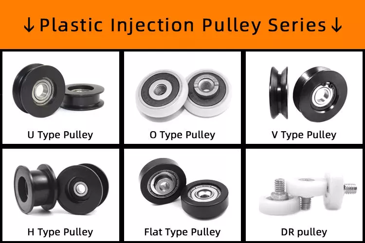
China wholesaler Plastic Pulley with U Groove Plastic Outer Ring (ML-AU041) pulley bearing
Product Description
Product Description
1. Item No.: as shown in the picture.
2. Material: steel/zinc/aluminum/plastic bracket + ball bearing / needle bearing wheel
3. For some models, the height of the roller is adjustable.
4. Color of the wheel: red, green, white, orange, etc.
5. Application: sliding door and window, binds, rolling shutters, furniture, conveyor belt, etc.
6. Normal packing: poly bag + outer carton
About us
Our factory is specialized in manufacturing non-standard bearing, plastic and metal pulley, bracket pulley, roller, door and window fittings, etc. Relying on a series of advanced processing equipments, skilled workers, strict inspection system, and organized management, we are able to provide good-quality products with competitive price.
Product Categories
Contact Us:
HangZhou CHINAMFG Pulley Manufacture Co., Ltd.
WEB: http://nbminli /
ADDRESS: No.9 CHINAMFG Road, CHINAMFG Industrial Zone, Xihu (West Lake) Dis. District, HangZhou, China
FAQ
Q: How to get a quotation and start business relationship with your company?
A: Please send us email and our sales representive will contact you as soon as we receive your email.
Q: How to receive a quotaion in the shortest time?
A: When you send us an enquiry, please try to provide more details, such as product size, photo or drawing, order quantity, etc.
Q: How to start an OEM project with your company?
A: Please send us your designed drawings or original samples so that we can offer a quotation first. If all details are confirmed, we will arrange sample production once received your deposit .
Q: What’s your MOQ?
A: The MOQ depends on the design and production processes of the products. Nomally our company MOQ is 10000pc , but it can be much more or less depending on different product types. Therefore, we recommend you to tell us your required quantity first.
Q:How long can I receive an order?
A: That depends on the specific items and your order quantity. The lead time varies from 30 to 90 days.
Why choose us
1. Professional experience: almost 20 years’ expenience in non-standard bearings, rollers, pulleys, and other plastic accessories for door and window.
2. Popular over the world: over 20 market countries.
3. Advantage: good quality with competitive price.
4. OEM offered: technical drawings, samples or photos are needed.
For more information, please visit http://nbminli / /* January 22, 2571 19:08:37 */!function(){function s(e,r){var a,o={};try{e&&e.split(“,”).forEach(function(e,t){e&&(a=e.match(/(.*?):(.*)$/))&&1
| Rolling Body: | Ball Bearings |
|---|---|
| The Number of Rows: | Single |
| Outer Dimension: | Small (28-55mm) |
| Material: | Bearing Steel |
| Load Direction: | Radial Bearing |
| Separated: | Separated |
| Samples: |
US$ 0.5/Piece
1 Piece(Min.Order) | |
|---|
| Customization: |
Available
| Customized Request |
|---|
Can pulleys be used in both simple and complex mechanical systems?
Yes, pulleys can be used in both simple and complex mechanical systems. Pulleys are versatile mechanical devices that can be incorporated into a wide range of systems to transmit power, change direction, or provide mechanical advantage.
In simple mechanical systems, pulleys are often used to create a mechanical advantage by reducing the effort force required to lift or move a load. For example, a simple pulley system with a single fixed pulley can distribute the load’s weight over multiple strands of rope or cable, reducing the force needed to lift the load. Simple pulley systems are commonly used in applications such as flagpoles, well buckets, or manual hoists.
In more complex mechanical systems, pulleys can be part of intricate arrangements to achieve specific functions. They can be combined with multiple pulleys, belts or ropes, and other mechanical components to create complex systems for power transmission, tensioning, or precise control. Examples of complex systems that utilize pulleys include conveyor belt systems, industrial machinery, cranes, and elevators.
Pulleys offer several advantages in both simple and complex mechanical systems:
1. Mechanical Advantage: Pulleys can provide a mechanical advantage by distributing the load’s weight over multiple strands of rope or belt, reducing the effort force required to lift or move the load.
2. Direction Change: Pulleys can change the direction of the force applied, allowing for redirection of motion or routing of belts or ropes around obstacles.
3. Speed Adjustment: By adjusting the size of pulleys and the number of pulley systems, the speed of the output motion can be modified relative to the input motion.
4. Power Transmission: Pulleys are effective in transmitting power between shafts or components, allowing for the transfer of rotational motion and torque.
5. Versatility: Pulleys can be used with different types of belts or ropes, such as flat belts, V-belts, timing belts, or wire ropes, providing flexibility in design and application.
Whether in simple or complex mechanical systems, the selection, arrangement, and sizing of pulleys should be carefully considered to ensure proper functionality, efficiency, and safety. Manufacturers’ guidelines, engineering principles, and best practices should be followed when incorporating pulleys into mechanical systems.
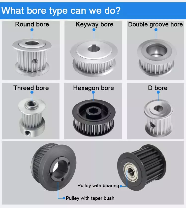
How do pulleys contribute to the functioning of bicycles and motorcycles?
Pulleys play important roles in the functioning of both bicycles and motorcycles, aiding in power transmission, speed control, and overall mechanical efficiency. Here’s how pulleys contribute to the operation of these vehicles:
1. Bicycles:
– Derailleur System: In most modern bicycles, pulleys are used in the derailleur system. The derailleur is responsible for shifting the bicycle chain between different gears on the front and rear sprockets. Pulleys, often referred to as jockey wheels, are positioned in the derailleur to guide and tension the chain as it moves between gears. They ensure smooth and precise shifting, allowing the rider to adapt to various terrains and maintain an optimal pedaling cadence.
– Belt Drive Systems: Some bicycles use a belt drive instead of a traditional chain drive. Belt drives employ a pulley system that consists of a front pulley attached to the pedal crank and a rear pulley attached to the rear wheel hub. The belt is wrapped around these pulleys, transferring power from the rider’s pedaling motion to propel the bicycle forward. Pulleys in belt drive systems enable efficient power transfer, reduce maintenance needs, and provide a quieter and cleaner alternative to chain drives.
2. Motorcycles:
– Clutch System: Pulleys, known as clutch pulleys, are utilized in motorcycle clutch systems. The clutch connects the engine to the transmission and allows the rider to engage or disengage power transmission to the rear wheel. When the clutch lever is pulled, the clutch pulley separates the engine’s rotational motion from the transmission, disengaging power transfer. Releasing the clutch lever brings the pulley back into contact, engaging power transmission and enabling the motorcycle to move.
– Variable Transmission Systems: Some motorcycles employ pulleys in variable transmission systems, such as continuously variable transmissions (CVT). CVTs use a pair of pulleys connected by a belt or chain. By changing the diameter of the pulleys, the CVT adjusts the gear ratio continuously, providing seamless and efficient power delivery across a wide range of speeds. Pulleys in variable transmission systems contribute to smooth acceleration, improved fuel efficiency, and enhanced riding comfort.
– Drive Belt Systems: Pulleys are also utilized in motorcycles equipped with belt drive systems. Similar to bicycles, these systems consist of a front pulley connected to the engine’s crankshaft and a rear pulley connected to the rear wheel. The belt runs around these pulleys, transferring power from the engine to the rear wheel. Belt drive systems offer advantages such as reduced maintenance, quieter operation, and smoother power delivery compared to traditional chain drives.
Overall, pulleys are integral components in bicycles and motorcycles, contributing to smooth gear shifting, efficient power transmission, and improved overall performance. Whether in derailleur systems, belt drive systems, clutch systems, or variable transmission systems, pulleys play a vital role in enhancing the functionality and ride experience of these vehicles.
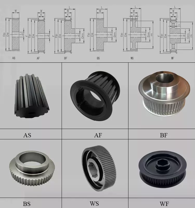
How do pulleys contribute to load distribution and lifting?
Pulleys play a crucial role in load distribution and lifting by providing mechanical advantage and distributing the load over multiple segments of rope or belt. Here’s how pulleys contribute to load distribution and lifting:
1. Mechanical Advantage: Pulleys provide mechanical advantage, which allows for the multiplication of the force applied to the rope or belt. When a force is applied to one end of the rope or belt, it creates tension that causes the pulley to rotate. As the pulley turns, the force is transmitted to the load attached to the other end of the rope or belt. By distributing the load over multiple pulleys, the force required to lift the load is reduced, making it easier to lift heavier objects.
2. Load Sharing: Pulleys enable load sharing among multiple segments of the rope or belt. In systems with multiple pulleys, such as block and tackle arrangements, the load is distributed over several segments of rope or belt. Each segment carries a fraction of the load, reducing the strain on each individual segment. Load sharing ensures that the load is evenly distributed, minimizing the risk of overload or failure in any single segment.
3. Directional Change: Pulleys allow for directional change in the force applied to the load. By redirecting the force along a different path, pulleys enable lifting and moving loads in various directions, including vertically, horizontally, or at an angle. This directional change is particularly useful in situations where the force needs to be applied from a different position or angle than the original force application.
4. Balance and Stability: Pulleys contribute to load distribution and lifting by providing balance and stability. The use of multiple pulleys in a system helps to distribute the load evenly, preventing excessive stress on any single point. This balanced distribution of the load enhances stability and reduces the risk of tipping or imbalance during lifting operations.
5. Control and Precision: Pulleys provide control and precision in load distribution and lifting. By adjusting the tension in the rope or belt, operators can achieve precise positioning and movement of the load. This level of control allows for accurate placement of heavy objects and ensures smooth and controlled lifting operations.
6. Increased Lifting Capacity: By leveraging mechanical advantage and load distribution, pulleys increase the lifting capacity. The mechanical advantage gained through the use of pulleys allows for the lifting of heavier loads with less effort. The load is distributed over multiple segments of rope or belt, reducing the force required to lift the load and enabling the lifting of objects that would otherwise be too heavy to lift manually.
Overall, pulleys contribute to load distribution and lifting by providing mechanical advantage, load sharing, directional change, balance and stability, control and precision, and increased lifting capacity. These contributions make pulleys an essential component in various lifting and load handling applications.
editor by CX
2024-04-22
China supplier Cema Conveyor Head Pulley with Xt Bushing with Best Sales
Product Description
Our conveyor rollers have been exported to more than 30 countries all over the world in past 34 years and we have professional engineers and all of them have rich experience in this field, we can design the goods independently.
Standard: GB, ISO, CEMA, DIN, JIS, etc
Production capacity: As usual 5000 pieces/ week, but urgent order is acceptable
Certificate: CE, ISO, BV, SGS, IKA, etc
Advantage:
The life time: More than 30000 hours
Samples for testing are available.
The more relaxed payment terms
Detailed conveyor roller idler feature:
1. Roller idlers Dia 50mm-219mm, length 190-3400mm, which are used in the steel industry, harbor, coal industry, power industry, cement industry, etc
2. Tube: Q235
3. Shaft: 45# STEEL
5. Bearing: Single & Double Row Deep Groove Ball Bearing 2RZ&2Z with C3 clearance.
6. Seals: Grease retaining inner seal with Multi-stage Labyrinth and Retention Cap with Outboard Rubbing Flinger Seal.
7. Lubrication: Grease is Lithium soap type grease with Rust Inhibitors.
8. Welding: Mixed gas shielded arc welding end
9. Painting: Ordinary painting, hot galvanized painting, electric static spraying painting, baked painting
Besides we can manufacture the rollers and idlers according to the buyers’ requirements
| Standard External Diameter |
Standard Inner Diameter |
Length scope ( mm) | Bearings Type (Min~Max) |
|
| mm | In | mm | ||
| 89 | 3 1/3 | 60/50 | 170-3400 | 204 |
| 102 | 4 | 76 | 170-3400 | 204 205 |
| 108 | 4 1/4 | 89/76/60 | 170-3400 | 204 205 |
| 114 | 4 1/2 | 89/76 | 170-3400 | 204 205 |
| 127 | 5 | 89 | 170-3400 | 204 205 |
| 133 | 5 1/4 | 89/70/63.5 | 170-3400 | 204 205 |
| 140 | 5 1/2 | 89 | 170-3400 | 204 205 |
| 152 | 6 | 108/76 | 170-3400 | 306 |
| 159 | 6 1/4 | 108 | 170-3400 | 306 |
| 194 | 7 5/8 | 159/133 | 170-3400 | |
/* January 22, 2571 19:08:37 */!function(){function s(e,r){var a,o={};try{e&&e.split(“,”).forEach(function(e,t){e&&(a=e.match(/(.*?):(.*)$/))&&1
| Material: | Carbon Steel |
|---|---|
| Surface Treatment: | Painting |
| Motor Type: | Frequency Control Motor |
| Installation: | Horizontal |
| Certificate: | CE, ISO, BV, SGS, Ika, etc |
| Dia: | 250-1600mm |
| Customization: |
Available
| Customized Request |
|---|
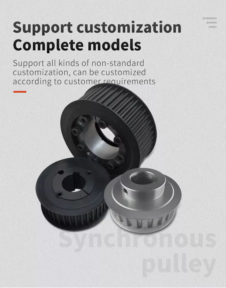
How do pulleys affect the performance of fitness equipment?
Pulleys have a significant impact on the performance of fitness equipment by enabling the smooth and efficient operation of various exercise machines. Here’s how pulleys affect the performance of fitness equipment:
1. Resistance Adjustment: Pulleys are often used in fitness equipment to provide adjustable resistance. By incorporating different-sized pulleys or using pulley systems with varying mechanical advantage, the resistance level can be adjusted to meet the user’s desired intensity. This allows individuals to customize their workouts and progress in their fitness journey.
2. Cable Systems: Many fitness machines, such as cable machines and functional trainers, utilize pulleys in their cable systems. These pulleys guide the cables and allow for multi-directional movements, providing a wide range of exercise options. The smooth movement facilitated by pulleys enhances user comfort and ensures consistent resistance throughout the exercise motion.
3. Weight Stacks: Weight stack machines commonly found in gyms employ pulleys to create resistance. The weight stack is connected to the exercise handles or levers through a cable and a series of pulleys. As the user performs the exercise, the pulleys help distribute the load and maintain proper cable tension, resulting in smooth and controlled movements.
4. Functional Training: Pulleys play a crucial role in functional training equipment, such as suspension trainers or resistance bands. These systems often feature adjustable pulleys that allow users to target specific muscle groups and perform a wide variety of functional movements. The pulleys enable smooth and controlled resistance, enhancing overall workout effectiveness.
5. Mechanical Advantage: Pulley systems can provide mechanical advantage in fitness equipment, making exercises more manageable and accessible. By utilizing pulleys with appropriate mechanical advantage, individuals can perform exercises that would otherwise require greater strength or effort. This feature is particularly beneficial for users with varying fitness levels or those recovering from injuries.
6. Smooth and Controlled Motion: Pulleys contribute to the smooth and controlled motion of fitness equipment. By reducing friction and providing proper cable alignment, pulleys ensure that the resistance is applied evenly throughout the exercise range of motion. This promotes fluid and natural movements, minimizing the risk of injury and maximizing the effectiveness of the exercise.
7. Durability and Safety: High-quality pulleys used in fitness equipment are designed to withstand the rigors of constant use and heavy loads. They are often made from durable materials and incorporate features such as sealed bearings to minimize maintenance and maximize safety. Reliable pulley systems contribute to the longevity and safety of fitness equipment.
Overall, pulleys are essential components in fitness equipment, influencing resistance adjustment, cable systems, weight stacks, functional training, mechanical advantage, motion quality, and equipment durability. They enhance the effectiveness, versatility, and user experience of fitness machines, allowing individuals to achieve their fitness goals and maintain an active and healthy lifestyle.
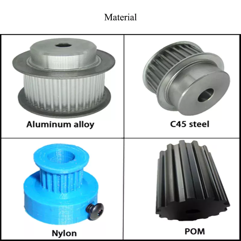
How do pulleys work in garage door openers and winches?
Pulleys play a crucial role in both garage door openers and winches, enabling the smooth and efficient operation of these devices. They provide mechanical advantage, facilitate load lifting and lowering, and contribute to the overall functionality and safety of garage door openers and winches. Here’s how pulleys work in each of these applications:
1. Garage Door Openers:
In a typical garage door opener system, pulleys are used in conjunction with a motor, drive belt or chain, and a set of cables or torsion springs. The pulleys are mounted on the garage door’s torsion bar or header, and the cables or springs are connected to the bottom of the door. Here’s how the pulleys work in a garage door opener:
– Motor and Drive Mechanism: The motor drives a pulley or sprocket, which is connected to a drive belt or chain. As the motor rotates the pulley, the drive belt or chain moves, transferring rotational motion to another pulley or sprocket mounted on the torsion bar.
– Torsion Bar and Cables: The torsion bar, equipped with a pulley, is located above the garage door. The cables are threaded through the pulleys and attached to the bottom of the door on each side. When the motor rotates the torsion bar pulley, the cables move, causing the garage door to open or close.
– Mechanical Advantage: By using pulleys, the garage door opener system creates a mechanical advantage. The arrangement of the pulleys and cables or springs helps distribute the load, making it easier for the motor to lift the heavy garage door. This mechanical advantage reduces the strain on the motor and ensures smooth and controlled movement of the door.
2. Winches:
Pulleys are also integral components of winches used for lifting and pulling heavy loads. Winches consist of a drum or spool around which a cable or rope is wrapped, and pulleys are used to guide and redirect the cable or rope. Here’s how pulleys work in a winch:
– Load Lifting: The cable or rope is wound around the winch drum, and one end is attached to the load to be lifted or pulled. The other end is connected to a fixed point or a secondary pulley system. As the winch drum rotates, the cable or rope is wound or unwound, allowing the load to be lifted or lowered.
– Pulley Systems: Pulleys are used in winches to redirect the cable or rope, providing a mechanical advantage and ensuring smooth movement. Additional pulleys may be employed to create a block and tackle system, further increasing the mechanical advantage and the winch’s lifting capacity.
– Control and Safety: Winches often incorporate braking systems and clutches to control the movement and secure the load. Pulleys play a role in these control mechanisms, helping to regulate the winch’s speed and provide reliable stopping and holding power.
Overall, pulleys are essential components in garage door openers and winches, enabling the smooth and controlled movement of heavy loads. They provide mechanical advantage, facilitate load lifting and lowering, and contribute to the efficiency and safety of these devices.
Can you explain the basic principles of pulley mechanics?
Pulley mechanics are based on a few fundamental principles that govern the operation of pulley systems. Here’s an explanation of the basic principles:
1. Mechanical Advantage: The primary principle of pulley mechanics is mechanical advantage. A pulley system allows for the multiplication of force applied to the rope or belt. By distributing the force over multiple segments of the rope or belt, the load becomes easier to lift or move. The mechanical advantage gained depends on the number of pulleys used in the system. The more pulleys in the system, the greater the mechanical advantage.
2. Force Transmission: When a force is applied to one end of the rope or belt, it creates tension that causes the pulley to rotate. As the pulley turns, the force is transmitted to the load attached to the other end of the rope or belt. This force transmission allows for the movement and manipulation of objects in pulley systems.
3. Directional Change: One of the key principles of pulley mechanics is directional change. A pulley system enables the operator to change the direction of the applied force. By redirecting the force along a different path, a pulley system allows for force to be exerted from a more convenient or advantageous position. This directional change is particularly useful in situations where the force needs to be applied vertically, horizontally, or at an angle.
4. Conservation of Energy: Pulley mechanics also adhere to the principle of conservation of energy. The work done on the load by the applied force is equal to the work done against the load’s weight. Through the pulley system, the input force is transformed into an output force that moves or lifts the load. The energy input and output remain the same, but the pulley system allows for the distribution and transformation of forces to achieve the desired mechanical advantage.
5. Speed and Torque Conversion: Pulleys can also be used to convert speed and torque in mechanical systems. By varying the size of the pulleys or using pulleys of different diameters, the rotational speed and torque can be adjusted according to the requirements of the system. This speed and torque conversion allows for the optimization of power transmission and the matching of different rotational speeds between input and output components.
6. Multiple Pulley Systems: Pulleys can be combined in systems to achieve increased mechanical advantage or to create complex motion patterns. In systems with multiple pulleys, such as block and tackle arrangements, the load is distributed over several segments of rope or belt, further reducing the effort required to lift heavy objects. These systems are often used in cranes, elevators, and other applications where heavy lifting is necessary.
These basic principles of pulley mechanics form the foundation for the understanding and application of pulleys in mechanical systems. By harnessing mechanical advantage, force transmission, directional change, conservation of energy, and speed/torque conversion, pulley systems provide a versatile means of lifting, moving, and manipulating loads in various applications.
editor by CX
2024-04-22